Application and maintenance of tension to transmission line in pipe

Active Publication Date: 2015-01-01
NEXTSTREAM WIRED PIPE LLC
View PDF1 Cites 9 Cited by
  • Summary
  • Abstract
  • Description
  • Claims
  • Application Information

AI Technical Summary

Benefits of technology

The patent describes a method for providing tension to a transmission line in a pipe. This is done by inserting the line into a channel in the pipe and applying tension to one end of the line while adding a second tension-load-supporting mechanism to the other end. The method also includes removing the first level of tension to maintain the second level of tension between the two mechanisms. The patent also describes a pipe assembly with the transmission line and two tension-load-bearing mechanisms to maintain tension along the line. The technical effect is to provide a reliable and adjustable tensioning mechanism for transmission lines in pipes, which can help to prevent damage or malfunctions in the line.

Problems solved by technology

When the transmission lines are slack in the well pipe, they may be damaged by fluids and debris flowing through the well pipe.

Method used


Image

  • Application and maintenance of tension to transmission line in pipe
  • Application and maintenance of tension to transmission line in pipe
  • Application and maintenance of tension to transmission line in pipe

Examples


Embodiment Construction

[0027]A detailed description of one or more embodiments of the disclosed apparatus and method are presented herein by way of example and not limitation with reference to the Figures.

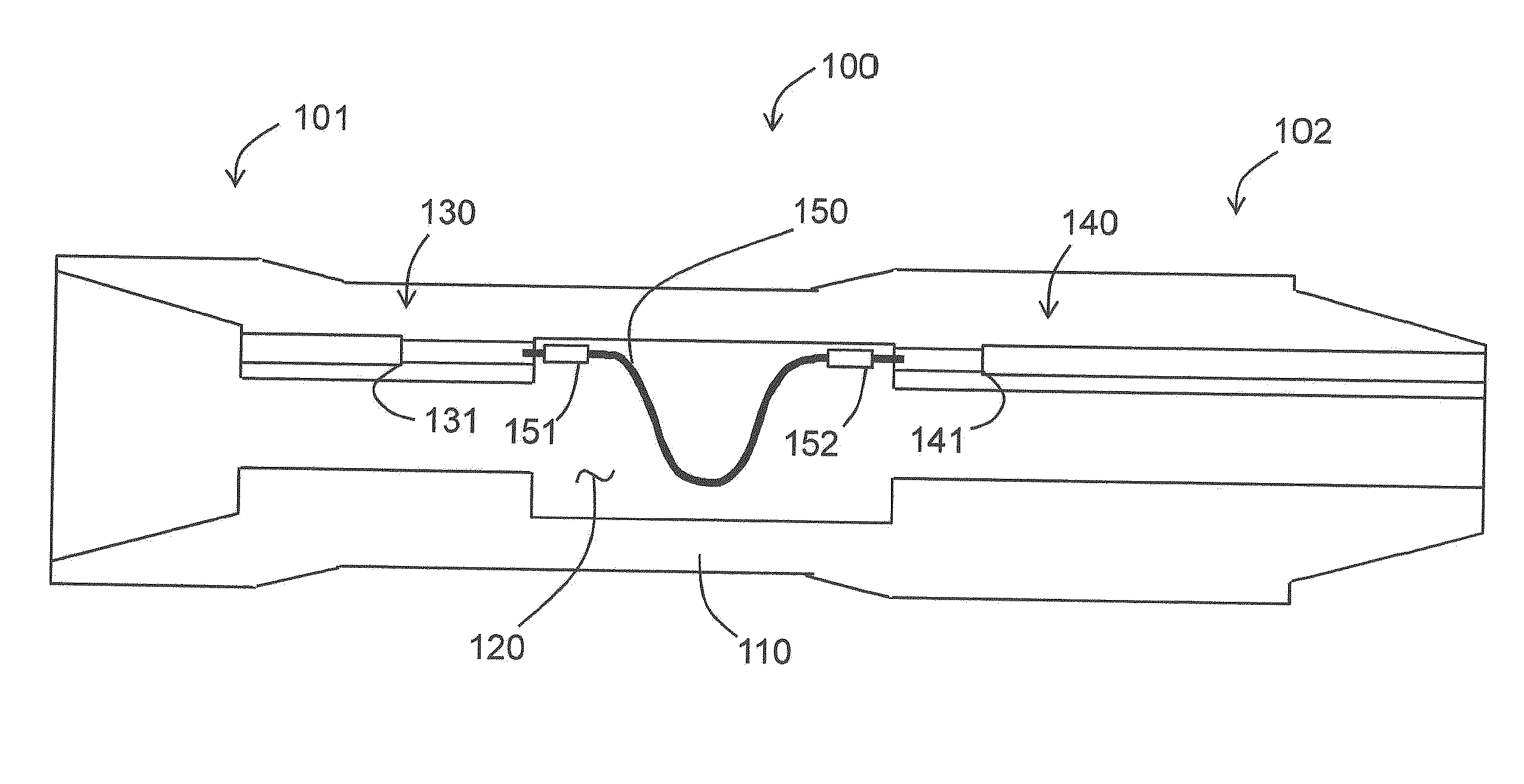
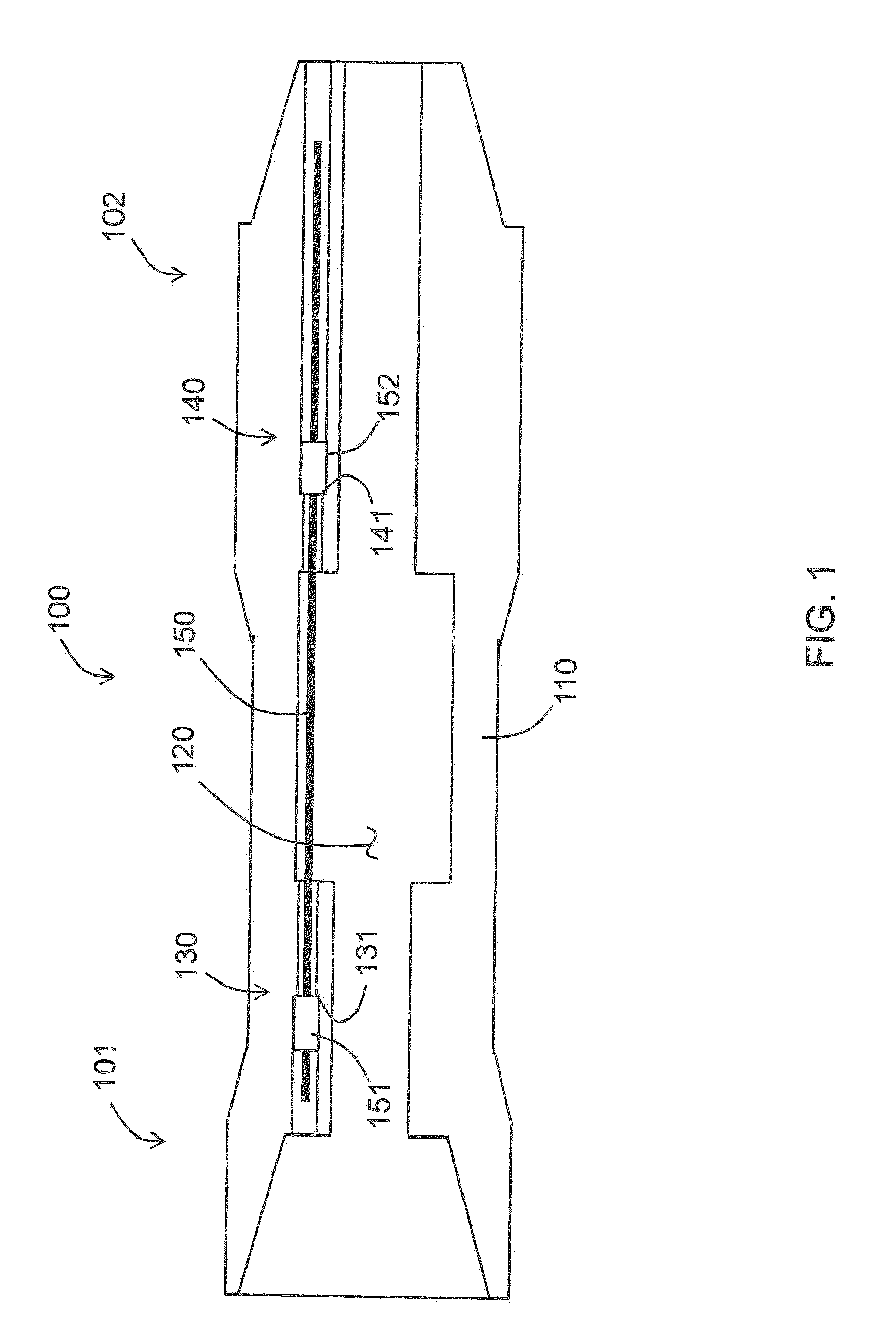
[0028]FIG. 1 illustrates a pipe segment 100 according to an embodiment of the invention. The pipe segment 100 may be a well pipe segment configured to connect to other well pipe segments to form a pipe in an oil well, or the pipe segment 100 may perform any other purpose. The pipe segment 100 includes a pipe body 110 that defines a main cavity 120. The main cavity 120 extends the length of the pipe segment 100 and is configured to permit fluid flow through the pipe segment 100. In embodiments of the invention, the main cavity 120 is coaxial with the pipe body 110.

[0029]The pipe body 110 includes a first end 101 and a second end 102. In FIG. 1, the first end 101 has a box configuration and the second end 102 has a pin configuration. The pin end is configured to fit into a box end of an adjacent pipe segme...


PUM

PropertyMeasurementUnit
Forceaaaaaaaaaa
Diameteraaaaaaaaaa
Tensionaaaaaaaaaa

Abstract

Disclosed is a method and assembly for providing tension to a transmission line in a pipe. The method includes inserting a transmission line into a transmission line channel of a pipe. The transmission line has a first end and a second end, the transmission line being inserted into a first end of the pipe second-end-first. The transmission line has a first tension-load-supporting mechanism attached to the first end of the transmission line. The method includes applying a first level of tension to the transmission line in the pipe and applying a second tension-load-supporting mechanism to the second end of the transmission line while the first level of tension is applied to the transmission line. The method further includes removing the first level of tension from the transmission line to maintain a second level of tension along the transmission line between the first and second tension-load-supporting mechanisms.

Description

BACKGROUND OF THE INVENTION[0001]In oil and gas drilling and completion systems, power and data are communicated between downhole devices and uphole devices via transmission lines that extend along well pipes. When the transmission lines are slack in the well pipe, they may be damaged by fluids and debris flowing through the well pipe.BRIEF DESCRIPTION OF THE INVENTION[0002]Disclosed herein is a method for providing tension to a transmission line in a pipe. The method includes inserting a transmission line into a transmission line channel of a pipe. The transmission line has a first end and a second end, the transmission line being inserted into a first end of the pipe second-end-first. The transmission line has a first tension-load-supporting mechanism attached to the first end of the transmission line. The method includes applying a first level of tension to the transmission line in the pipe and applying a second tension-load-supporting mechanism to the second end of the transmiss...

Claims


Application Information

Patent Timeline
IPC IPC(8): H02G1/00H02G3/02
CPCH02G1/00H02G3/02Y10T29/49826E21B17/206H02G1/06E21B17/003
Inventor KOPPE, MICHAELMUELLER, STEPHANRODERS, INGOSCHULZ, RENERAHN, HENNINGBUDA, ROBERTBENEDICT, DETLEVREISEWITZ, JULIAFLOERKE, HELMUT
Owner NEXTSTREAM WIRED PIPE LLC
Why Eureka
Try Eureka