Power management method and system

a power management and power technology, applied in the field of power management methods and systems, can solve the problems of inability to accurately monitor in real time, needless expenditure and waste, and handicapped distribution companies and similar entities in the united states

Inactive Publication Date: 2006-11-07
STEWART WILLIAM L
View PDF19 Cites 227 Cited by
  • Summary
  • Abstract
  • Description
  • Claims
  • Application Information

AI Technical Summary

Benefits of technology

[0006]The present invention provides a system and method for gathering data from one or more inductive couplers. The collected data reflects power surges, demand shifts, and system breakdowns on a real time or near real time basis. Data collection may be timed by reference to an atomic clock signal in order to obtain accurate results from a plurality of locations at once. The system provides the capability of using the collected data in conjunction with stored data, such as historical data, local and nation power grid layout data, topographical information and dynamic information such as weather data to identify, characterize and locate power transmission problems and conditions that need attention.

Problems solved by technology

Utility companies, power distribution companies and similar entities in the United States are currently handicapped by an inability to accurately monitor in real time the state of power lines and distribution grids.
Thus, problems and inefficiencies often go undetected, resulting in needless expenditures and waste.

Method used


Image

  • Power management method and system
  • Power management method and system
  • Power management method and system

Examples


Embodiment Construction

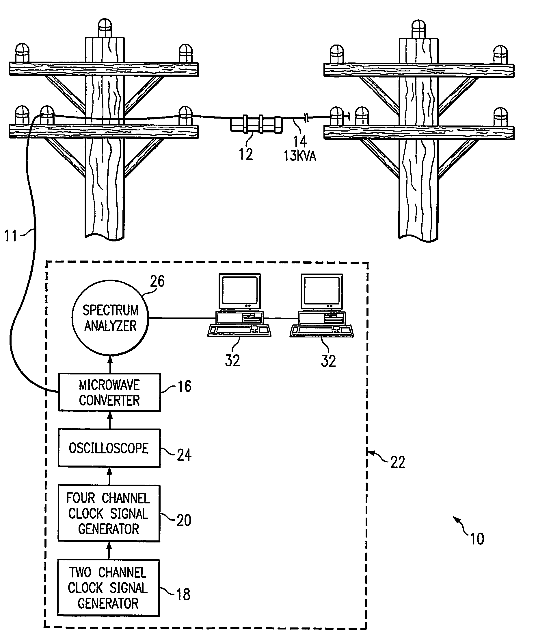
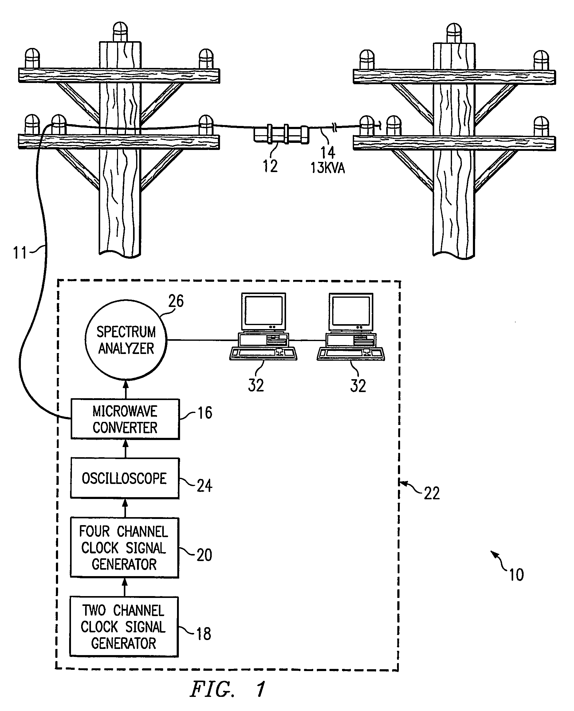
[0013]According to one embodiment of the invention as shown in FIGS. 1 and 2, a power management system 10 according to the invention includes one or more sensors (inductive couplers) 12 disposed in proximity to one or more power transmission lines 14. In practice, coupler 12 is clamped onto the power line at a convenient location in order to detect fluctuations in the voltage and current flowing through transmission line 14. As set forth in detail below, inductive coupler 12 includes an antenna and coils each of which are connected via a microwave cable 11 to a microwave converter 16 such as a HP model 8902 B analyzer, which filters the signals. Microwave cable 11 is configured similarly to a standard coaxial cable with a center conductor and an annular conductive shield, except that the shield of microwave cable 11 is typically a foil or layer of conductive material as opposed to the mesh used in typical coaxial cable. In the system illustrated in FIGS. 1 and 2, the center conduct...


PUM


Abstract

The present invention provides a new application for an inductive coupler (12) used proximate a power transmission line (14). The magnetic field based power measurement method and system discussed herein in unique and differs from the prior technology by using near-real time intervals and periods that occur systemically in parallel with electrical systems rather than an accumulated period with little or no active capacity or proactive features. The inductive coupler (12) described herewith is used to collect, measure, and/or extract electromagnetic changes.

Description

TECHNICAL FIELD[0001]The invention relates to management and distribution of electrical power, and in particular systems for monitoring the state of electrical power lines and distribution grids on a real time or near real time basis.BACKGROUND OF THE INVENTION[0002]Utility companies, power distribution companies and similar entities in the United States are currently handicapped by an inability to accurately monitor in real time the state of power lines and distribution grids. Thus, problems and inefficiencies often go undetected, resulting in needless expenditures and waste. The present invention is designed to address and rectify this situation.[0003]Electrical power in the United States is largely transmitted in the form of alternating current at a predetermined frequency most frequently 60 Hz. As is known, when current passes through a transmission line, it generates an electro magnetic field that varies in frequency and intensity with the current flowing through the line. Thes...

Claims


Application Information

Patent Timeline
Patent Type & Authority Patents(United States)
IPC IPC(8): G08B21/00H02J13/00G01R15/14G01R15/18G01R15/20G08C21/00
CPCG01R15/142G01R15/181
Inventor STEWART, WILLIAM L.
Owner STEWART WILLIAM L
Why Eureka
Try Eureka