Electronically Beam-Steerable Antenna Device

a beam-steering antenna and beam-steering technology, applied in the field of radio communication technology, can solve the problems of significantly reducing losses, not being able to combine in a compact structure an antenna element, and the dielectric board not being able to realize the active circui

Active Publication Date: 2014-03-20
RADIO GIGABIT
View PDF4 Cites 228 Cited by
  • Summary
  • Abstract
  • Description
  • Claims
  • Application Information

AI Technical Summary

Benefits of technology

[0033]According to yet another embodiment, the switching network is formed on semiconductor integrated circuits and the transceiver is formed by means of waveguide elements and is electrically connected to the high frequency dielectric board by means of a waveguide to microstrip transition. There are many different types of waveguide to microstrip transitions realized using high frequency dielectric boards in the prior art. Ability to connect the antenna device to the millimeter-wave waveguide transceiver is one more advantage of the present invention comparing with the prior art integrated lens antenna.
[0034]According to yet another embodiment, the present antenna device additionally comprises another switching network and the plurality of primary antenna elements comprises two arrays of primary antenna elements, wherein the first array is adapted to transmit a signal having a first linear polarization, the second array is adapted to receive a signal having a second linear polarization, orthogonal to the first linear polarization, and each switching network is adapted to independently control one of the two arrays of primary antenna elements. In this embodiment, the antenna device provides transmit and receive polarization diversity using one frequency band and one beam direction.
[0035]According to yet another embodiment, the present antenna device further comprises another switching network, each primary antenna element is adapted to transmit a signal having a first linear polarization and to receive a signal having a second linear polarization, orthogonal to the first linear polarization, and each switching network is adapted to independently control the plurality of primary antenna elements while transmitting a signal having the first linear polarization and receiving a signal having the second linear polarization, respectively. In this case, microstrip dual polarization antenna elements can be used as the primary antenna elements.
[0036]According to yet another embodiment, the primary antenna elements are microstrip antenna elements.
[0037]The dielectric lens in the antenna device according to the present invention forms a narrow beam and provides a beam deviation while scanning. The plurality of primary antenna elements and transmission lines are integrated on a flat surface of the dielectric lens. According to one embodiment the dielectric lens shape can be selected from the group comprising hemiellipsoidal shape with a cylindrical extension, hemispherical shape with a cylindrical extension, hemiellipsoidal shape with a truncated cone extension, and a shape of an ellipsoid truncated with a plane extending perpendicularly to an axis of the ellipsoid in proximity of a focus of the ellipsoid. From the prior art it is known that the length of the cylindrical extension is usually chosen to be close to the optical focus of the lens.
[0038]According to yet another embodiment, the presented antenna device is adapted to provide high data rate point-to-point millimeter-wave wireless communications for a radio relay station and to adjust a beam in case of initial adjustment or slight changes of orientation of a radio relay station due to such external effects as wind, vibrations, compression and / or extension of portions of the supporting structure with the temperature changes etc.

Problems solved by technology

The dielectric board does not allow realizing the active circuits but has significantly lower losses.
Thus, though in general antenna structures comprising dielectric lens and plurality of primary antenna elements are known in the prior art; however it was not possible by now to combine in compact structure an antenna elements supporting board, a switching network and antenna elements due to negative influence on each other.

Method used


Image

  • Electronically Beam-Steerable Antenna Device
  • Electronically Beam-Steerable Antenna Device
  • Electronically Beam-Steerable Antenna Device

Examples


Embodiment Construction

[0050]The present invention will be more fully understood from the description of the embodiments of realization of an electronically beam steerable integrated lens antenna for high data rate point-to-point millimeter-wave communications in radio relay station applications.

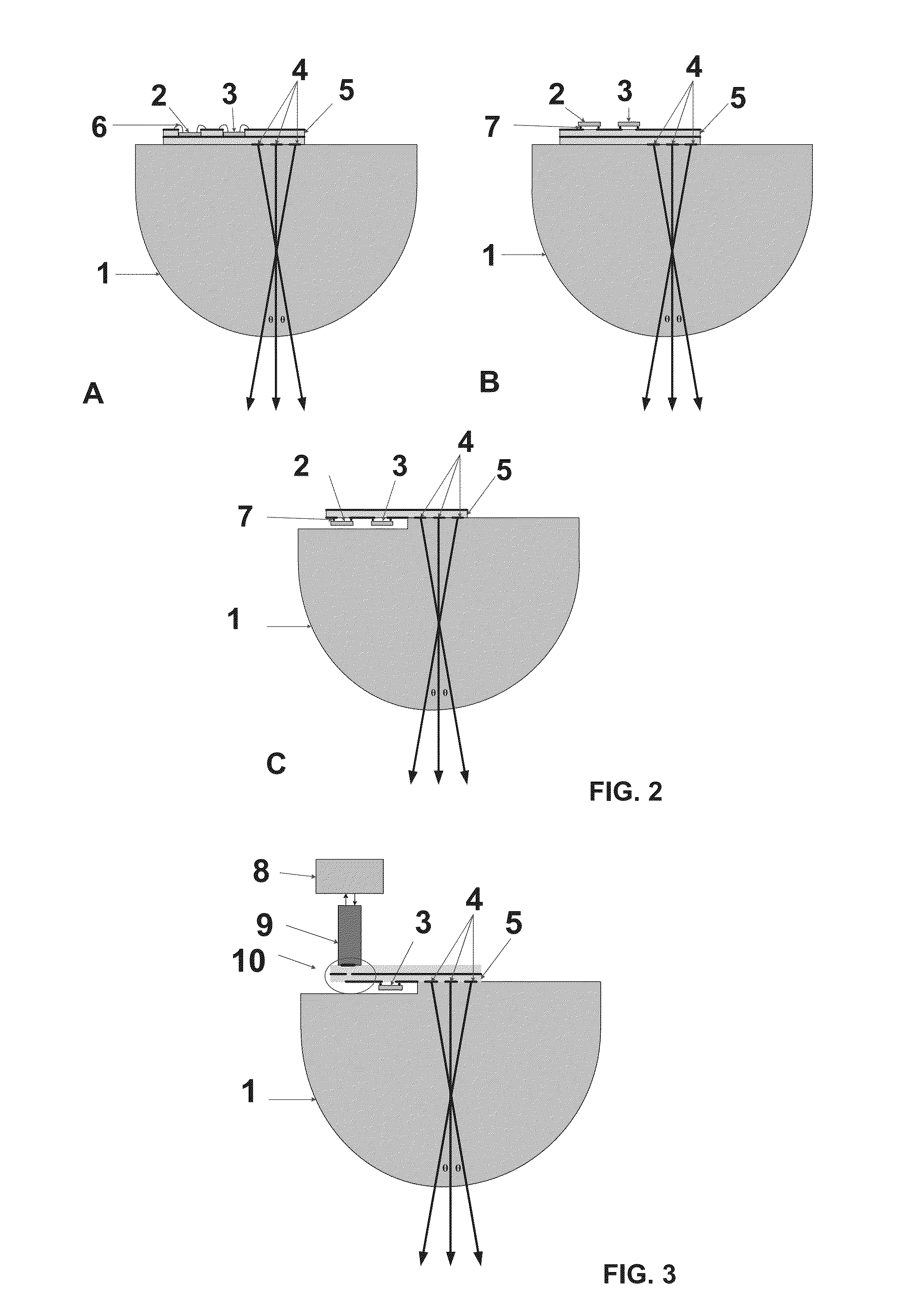
[0051]FIG. 2 shows axial sections of various embodiments of an integrated lens antenna according to the present invention.

[0052]In one embodiment, the integrated lens antenna comprises a homogeneous dielectric lens 1, primary antenna elements 4 and transmission lines for connecting thereof (not shown), a switching network 3 adapted to apply electric power to at least one primary antenna element, and a transceiver 2. The switching network 3 and the transceiver 2 are implemented as semiconductor integrated circuits. Primary antenna elements 4 are formed on high frequency dielectric board 5 and integrated in or on a flat surface of homogeneous dielectric lens 1. A multilayer printed or ceramic board can be used as a ...


PUM


Abstract

An electronically beam-steerable antenna device comprises a dielectric lens having at least one flat surface, a high frequency dielectric board, a plurality of at least one primary antenna element with at least one transmission line formed on the high frequency dielectric board, and a switching network electrically connected to the said plurality of at least one primary antenna element and at least one transmission line and adapted to apply electric power to the at least one primary antenna element. The switching network is a semiconductor integrated circuit mounted in or on the high frequency dielectric board, and the high frequency dielectric board with the plurality of at least one antenna element and at least one transmission line formed thereon is adjacent to the flat surface of the dielectric lens.The electronically beam steerable antenna device according to the present invention allows for electronic beam steering in a continuous angle sector while increasing radiation efficiency. The antenna device according to the present invention may be used for providing high data rate point-to-point millimeter-wave communications in radio relay station applications.

Description

CROSS-REFERENCE TO RELATED APPLICATIONS[0001]This application is a continuation-in-part of International application No. PCT / RU2011 / 000371, filed May 23, 2011, the content of which is incorporated herein by reference in its entirety.FIELD OF INVENTION[0002]The present invention generally relates to the field of radio communication technology and, more particularly, to electronically beam-steerable antenna devices. The present invention may be used for providing high data rate point-to-point millimeter-wave communications in radio relay station applications.RELATED ART[0003]Radio relay stations provide a high data rate point-to-point millimeter-wave communication at distances of about several kilometers in line-of-sight conditions. At the present time, radio relay stations use various radio frequency ranges with a carrier frequency in the range of 10 to 100 GHz. The increase of a carrier frequency is associated with constantly growing demands for higher communication system throughpu...

Claims


Application Information

Patent Timeline
Patent Type & Authority Applications(United States)
IPC IPC(8): H01Q3/24H04B7/00
CPCH04B7/00H01Q3/24H01Q19/062H01Q21/065H01Q19/06H01Q21/06
Inventor ARTEMENKO, ALEKSEY ANDREEVICHMASLENNIKOV, ROMAN OLEGOVICH
Owner RADIO GIGABIT
Why Eureka
Try Eureka