High density aircraft seat arrangement

a seat arrangement and high density technology, applied in the field of high density aircraft seat arrangement, can solve the problems of compromising packing efficiency, risking space waste, adversely affecting packing efficiency in certain aircraft cabin layouts, etc., and achieves the effect of not affecting the access or usability of the aisle, increasing the density of seated passengers, and reducing the width of the aisle at a higher level

Active Publication Date: 2015-01-01
SAFRAN SEATS GB LTD
View PDF6 Cites 24 Cited by
  • Summary
  • Abstract
  • Description
  • Claims
  • Application Information

AI Technical Summary

Benefits of technology

[0011]The present invention provides, in accordance with a first aspect, an aircraft cabin having a floor and a longitudinal axis, in which cabin there are installed a plurality of seat units including first and second seat units in a first row of seat units and a third seat unit in a second row of seat units, wherein (a) each seat unit includes a seat and a console adjacent to the seat, the seat being configurable between a bed mode and a seat mode, (b) the cabin includes an aisle extending parallel to the longitudinal axis, the first and second seat units being separated by the aisle, (c) the seats of each of the first, second and third seat units all face in the same direction, said direction being inclined to the longitudinal axis by a seat offset angle, (d) the console of the first seat unit is directly adjacent to the aisle and accommodates a foot-well for use by a passenger in the seat of the third seat unit, and (e) at least a part of the console of the first seat unit, in a region no higher than a first distance (for example 25 inches or 635 mm) from the floor, extends further into the aisle than the rest of the first seat unit in a region higher than the first distance from the floor. Thus, in accordance with the present invention valuable space can be utilised at a position relatively close to the floor, by a console that provides the function of a foot-well, where such space might otherwise be given up to the aisle. Decreasing the amount of space in the aisle at a low-level does not impede access or usability of the aisle, especially as the width of the aisle at a higher level can be more generous. Using space that might otherwise be aisle space in this manner effectively releases several inches worth of real estate across the width of the cabin for use by seated passengers. Given the value placed on useable space per passenger and on achieving increased density of seated passengers per unit area (sometimes referred to as “PAX density”), just creating a few extra inches space can make a very significant difference to the attractiveness of a LOPA to passengers and airlines alike.
[0015]Each seat unit may include a shell. The shell may extend around the back of the seat of the seat unit. The shell may be in the form of a privacy shell, which is provided to shield at least in part the passenger from other passengers in the vicinity. The shell may extend from the back of the seat towards the front of the seat in the region of the right hand side or left hand side of the seat, and preferably extends from the back of the seat towards the front of the seat both to the right of the seat and to the left of the seat, thus enhancing privacy. The shell of at least one of the first seat unit and the second seat unit may be so arranged that the second aisle-width-value mentioned above extends to a point on the shell (i.e. the shortest measured aisle width measured above the first distance above the floor is defined by the position of the shell). The second aisle-width-value may represent a distance from a point on the shell of the first seat unit and a point on the shell of the second seat unit. The shell of each seat unit preferably extends to a region above the console. The shell of each seat unit preferably extends to a region near to, but short of, the far end (in the direction from the seat to the console) of the console of the seat unit. A monitor may be provided in a shell; such a feature is described in further detail later.
[0023]The seat units in each row may include two seat units that are centred on the cabin floor at substantially the same distance along the cabin measured in a longitudinal direction. There may be three seat units in the same row that are so centred at substantially the same longitudinal distance along the cabin. One or both seat units that have a window seat may be positioned in staggered configuration in relation to the rest of the row to which the window seat belongs, such that that the seat unit having the window seat is centred on the cabin floor at a distance along the cabin measured in a longitudinal direction different from the corresponding distance for an inboard seat unit. Staggering outboard seat units in this manner can assist in creating a wider aisle and / or freeing-up more usable space. Preferably, however, all seat units in the same row are centred at substantially the same longitudinal distance along the cabin. Such a configuration provides a conventional look and feel to the cabin, in that seats are arranged in perpendicular columns and rows (albeit with the seats inclined when viewed from above relative to both the direction of the columns and the direction of the rows) such that ingress and egress walkways between rows of seats are perpendicular to the longitudinal axis. Preferably, each row of seat units extends in a direction perpendicular to the longitudinal axis.
[0044]The present invention also provides a seat unit, preferably a modular seat unit, being so configured as to be suitable for use as one of those installed in an aircraft cabin according any aspect of the invention described or claimed herein. Preferably, the seat unit has a shape / configuration that facilitates the creation of a high density business class LOPA. The seat unit includes a seat and a console adjacent to the seat, the seat being configurable between a bed mode and a seat mode, and the console of the seat unit accommodating a foot-well for use by a passenger sat in a different seat from that of the seat unit. The seat unit is advantageously arranged for installation in an aircraft cabin with like seat units to form at least a pair of directly adjacent columns of seat units, each column extending parallel to a common column axis, the seat of the seat unit facing a direction inclined to the column axis by a seat offset angle.
[0046]The parts that define the structure of each seat unit are advantageously independent of the parts that define the structure of any adjacent seat unit, and particularly parts that define the structure of any adjacent seat unit in the same row. In particular, each seat unit is a modular, stand-alone unit where no element or structure of the seat unit is connected to (other than by the aircraft structure) or shared with any other adjacent seat unit. For example, the console of each seat unit may be defined by walls that are not shared by an adjacent console or structure in the same row. In the prior art, adjacent consoles can share a wall thus providing a space-saving, but in this aspect of the invention, the extra space required by requiring each console to be defined by its own structure is deemed to be acceptable in view of the potential advantages provided by the modular and flexible design.

Problems solved by technology

Having a long seat pitch can compromise on packing efficiency, if the length of cabin is not close to an integer number multiplied by the seat pitch.
Increasing the seat offset angle may also create areas of space between seat units and cabin walls or between seat units and an aisle that could risk wasting space if not utilised wisely.
However, the seats being arranged to face parallel to the longitudinal axis of the cabin translates into a relatively long pitch of seat, which may adversely affect packing efficiency in certain aircraft cabin layouts.

Method used


Image

  • High density aircraft seat arrangement
  • High density aircraft seat arrangement
  • High density aircraft seat arrangement

Examples


Embodiment Construction

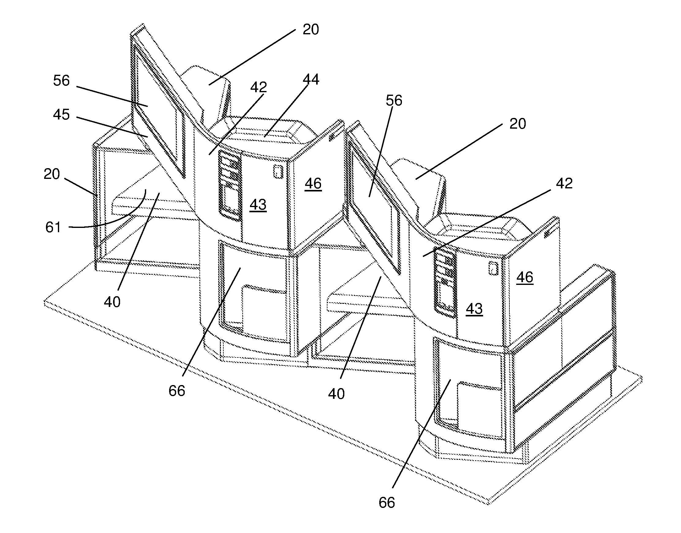
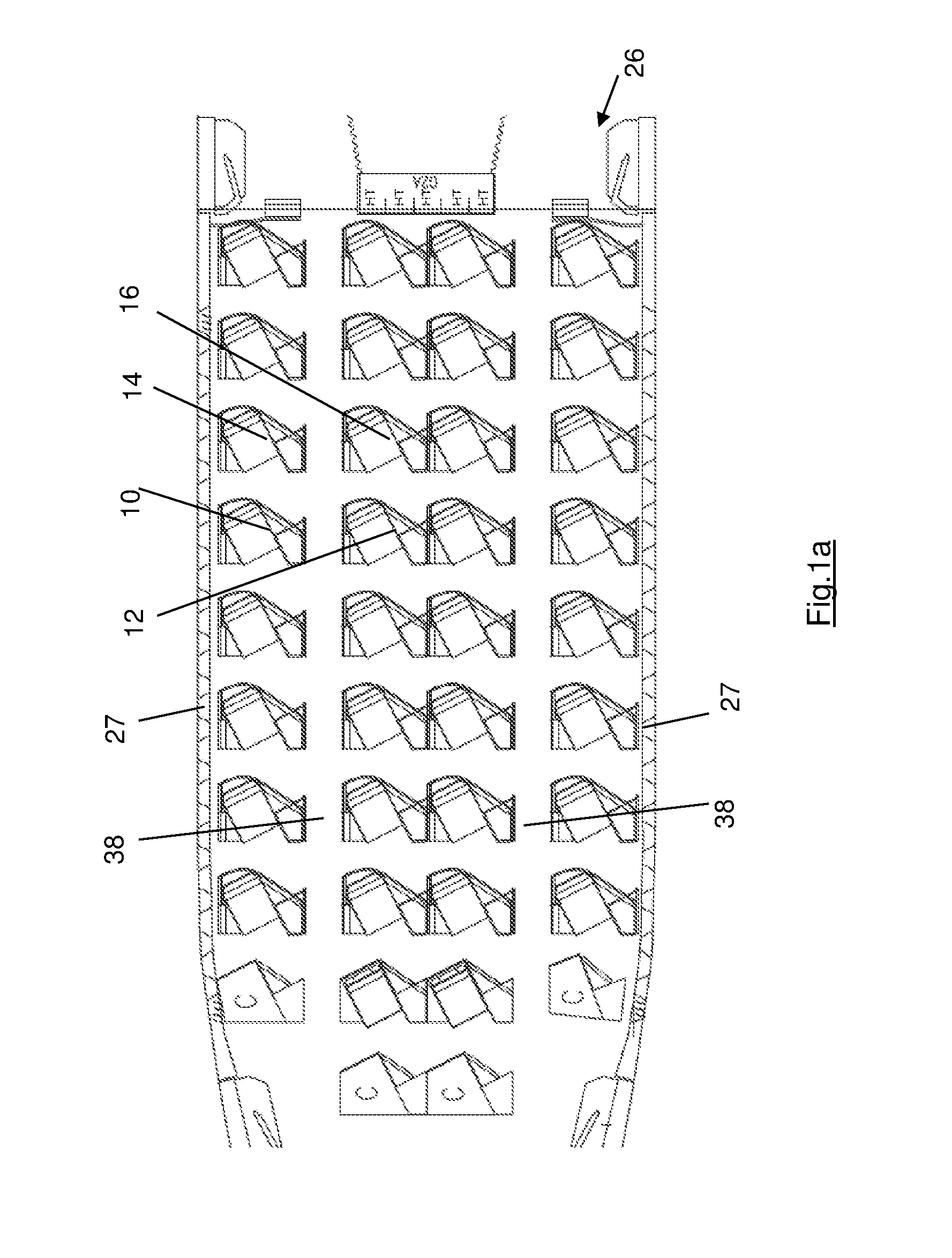
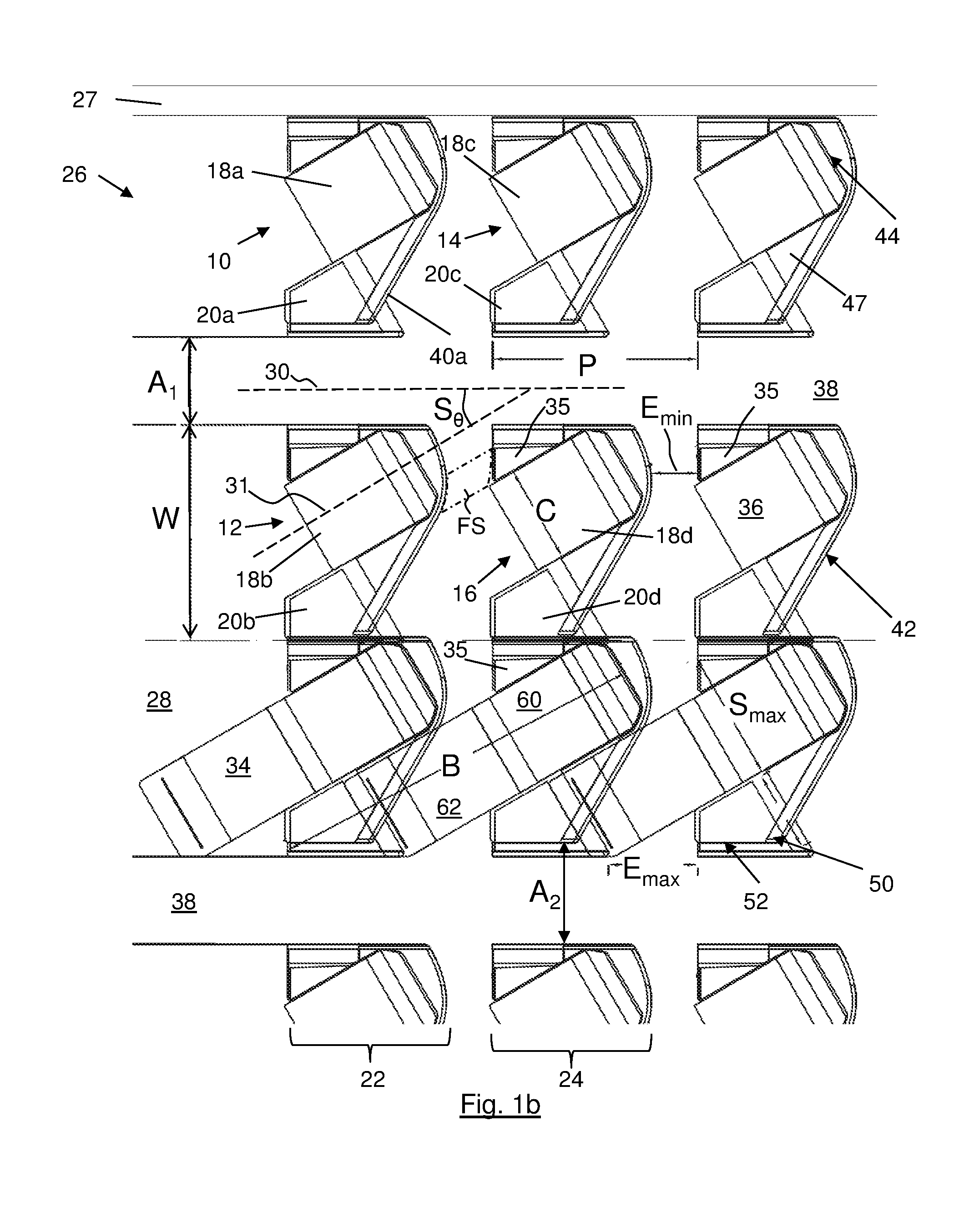
[0066]FIGS. 1a and 1b show in plan view part of a LOPA of a high density business class seat arrangement according to a first embodiment of the present invention. The seat arrangement comprises a set of seat units 10 arranged in multiple rows 22, 24 in an aircraft cabin 26, in this case the upper deck of an Airbus A380 aircraft. The seat units each comprise a seat 18 and an associated adjacent console 20. The seats are each configurable between a bed mode 34 and a seat mode 36 and each face in the same direction 31, which is one inclined to the longitudinal axis 30 of the cabin by about 30 degrees (the “seat offset angle” Sθ).

[0067]FIG. 1b shows part only of the FIG. 1a layout and thus shows three rows of four seats, the three leftmost seats (looking towards the nose of the aircraft) only being partly shown in FIG. 1b. All seat units 10 are of substantially the same size and shape resulting in a modular and consistent construction and installation of the seats. The seat units shown ...


PUM


Abstract

An aircraft cabin (26) has a plurality of seat units (10) including first (10) and second (12) seat units in a first row (22) and a third seat unit (14) in a second row (24). The first and second seat units (10, 12) are separated by an aisle (38). The seats all face in the same direction (31), said direction (31) being inclined to the longitudinal axis (30) by a seat offset angle (Sθ), and are configurable between a bed mode and a seat mode. A console (20a) of the first seat unit (10) is directly adjacent to the aisle (38) and accommodates a foot-well (40) for use by a passenger in the seat (18c) of the third seat unit (14). At least a part of the console (20a) of the first seat unit (10), in a region no higher than a first distance from the floor, extends further into the aisle (38) than the rest of the first seat unit (10) in a region higher than the first distance from the floor.

Description

TECHNICAL FIELD[0001]The present invention concerns an aircraft seat arrangement, preferably a high density aircraft seat arrangement, where the seats are convertible to beds and are for use in a cabin class superior to standard / economy seating arrangements, for example a business class cabin space. More particularly, but not exclusively, this invention concerns an aircraft cabin in which there are installed a plurality of seat units arranged in a plurality of rows, especially business class seat units.BACKGROUND OF THE INVENTION[0002]When designing a business and / or premium economy seat and corresponding LOPA (Layout of Passenger Accommodations) there are the inherently conflicting requirements of providing the feeling of space and comfort for the passenger whilst providing a high density seating configuration to maximise revenues for airlines. Passengers typically expect a lie-flat bed and a personal and private space, with access to storage areas, a personal TV / VDU monitor, a tab...

Claims


Application Information

Patent Timeline
Patent Type & Authority Applications(United States)
IPC IPC(8): B64D11/06
CPCB64D11/06B64D11/0601B64D11/0606B64D11/0641B64D11/0646B60N2/34B60N2/01B64D11/0604
Inventor ERSAN, ALINICHOLAS, RICHARDMCKEEVER, JOHN
Owner SAFRAN SEATS GB LTD
Why Eureka
Try Eureka