Lighting device

a technology of light guide member and light guide member, which is applied in the direction of interior lighting, lighting and heating equipment, transportation and packaging, etc., can solve the problems of unevenness, difficult to arrange and fix the light guide member, and the light guide member is easily bent or warped. , to achieve the effect of easy bent or warped

Active Publication Date: 2015-01-01
TOYOTA BOSHOKU KK
View PDF2 Cites 18 Cited by
  • Summary
  • Abstract
  • Description
  • Claims
  • Application Information

AI Technical Summary

Benefits of technology

[0007]The light guide member included in such a lighting device is easily bent or warped. Therefore, it is difficult to arrange and fix the light guide member surely in a correct position in assembling the

Problems solved by technology

The light guide member included in such a lighting device is easily bent or warped.
Therefore, it is difficult to arrange and fix the light guide member surely in a correct position in assembling the li

Method used


Image

  • Lighting device
  • Lighting device
  • Lighting device

Examples


first embodiment

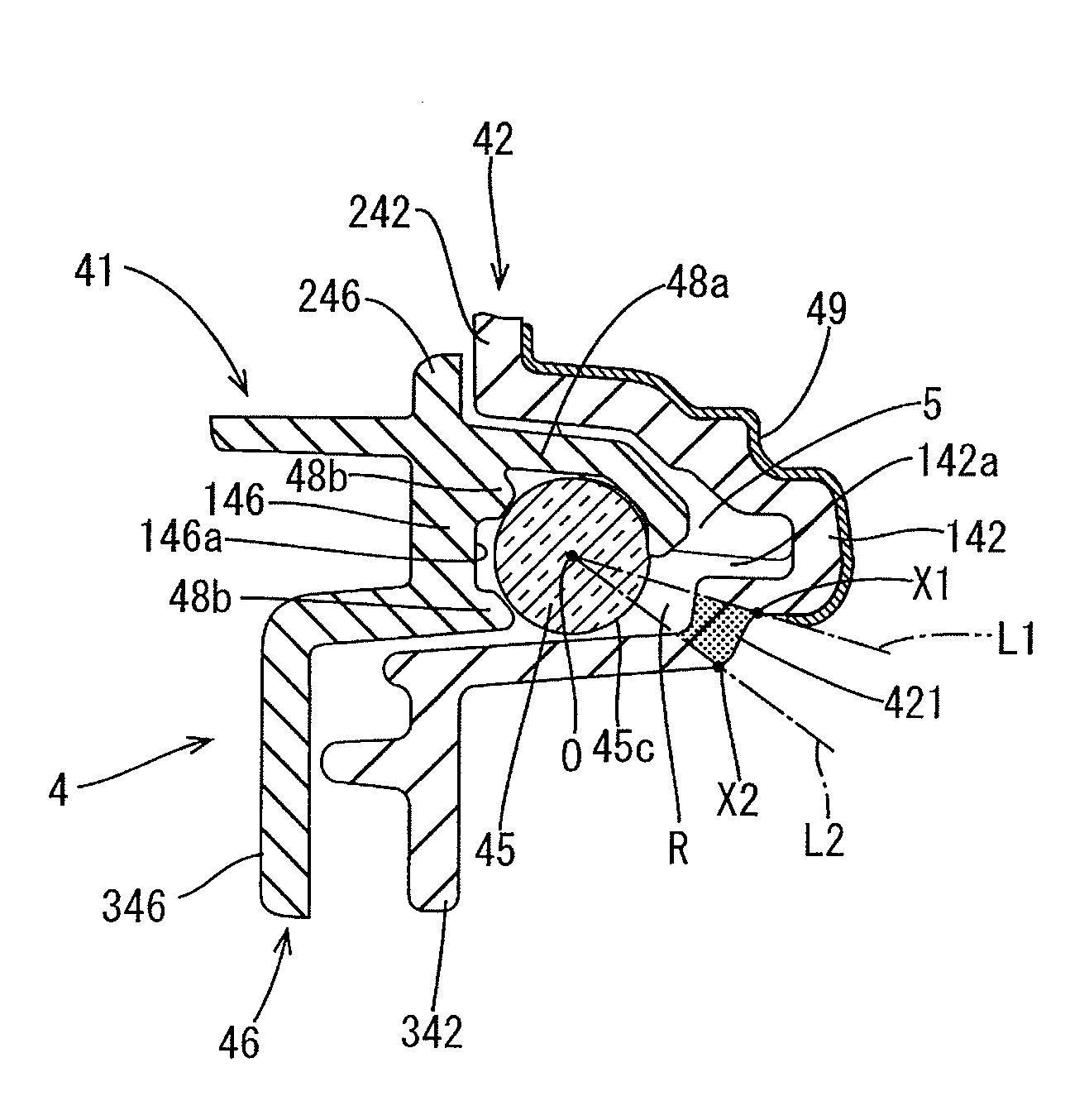
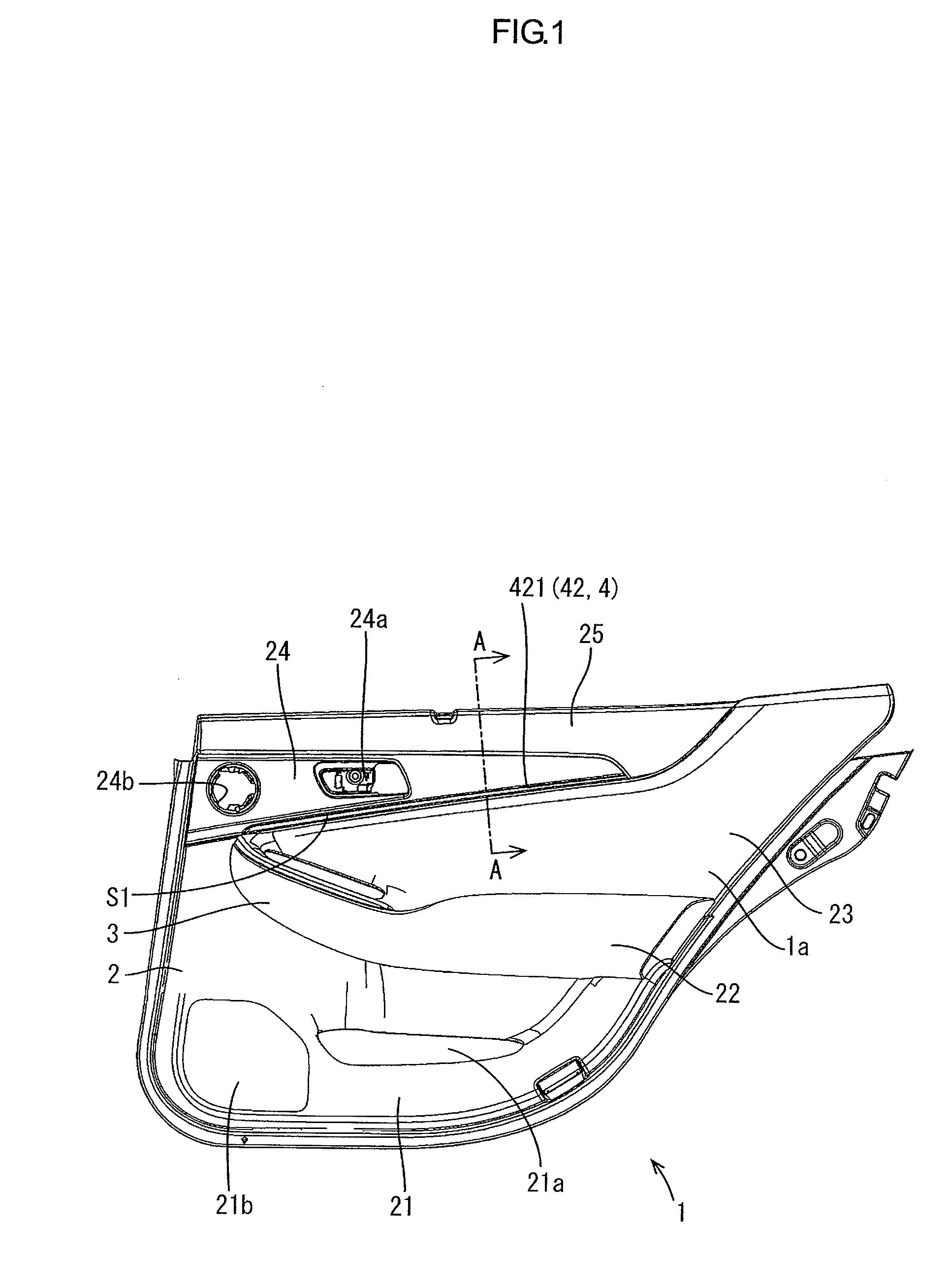
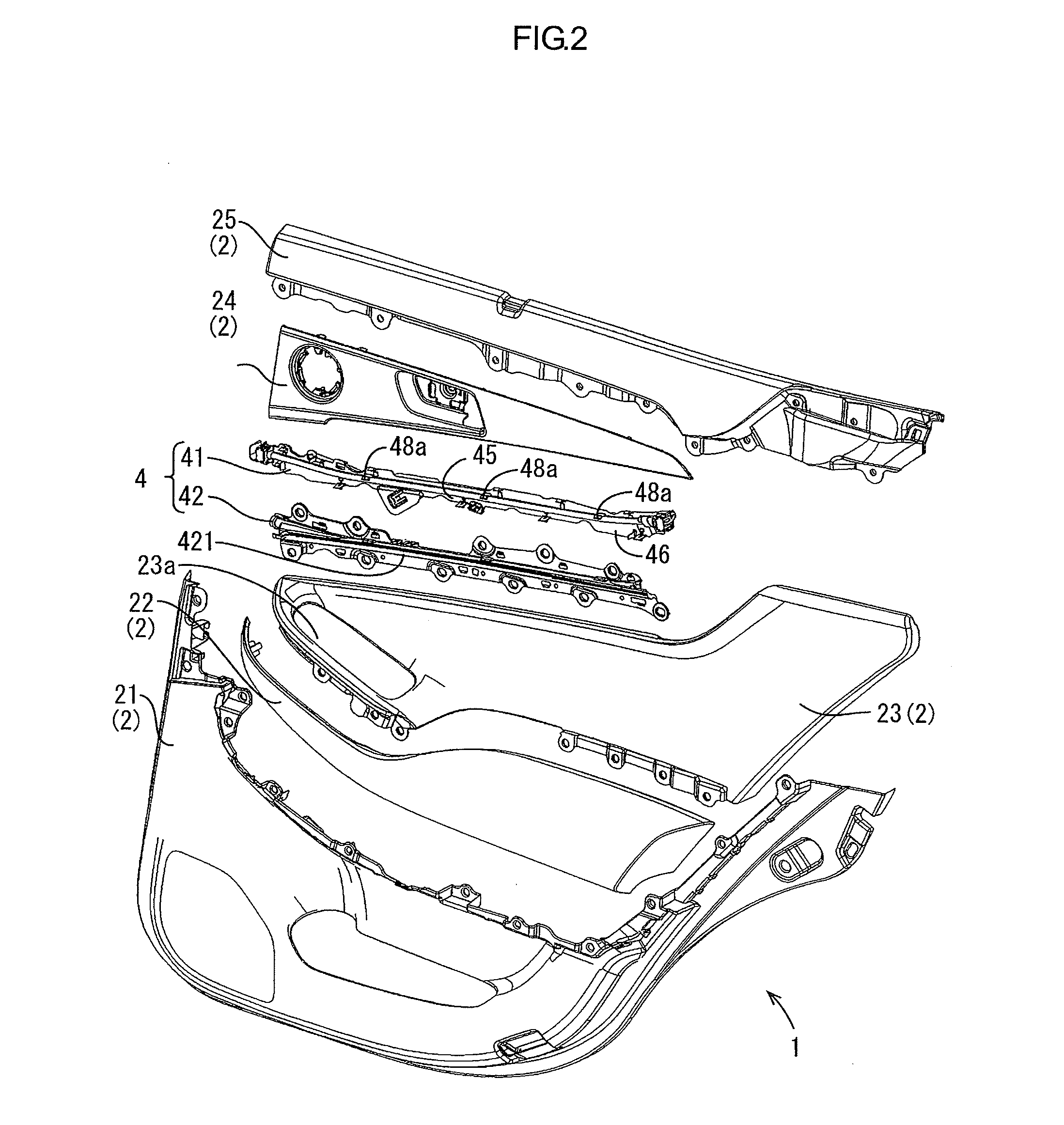
[0024]A first embodiment will be described with reference to FIGS. 1 to 9. In this embodiment, a door trim 1 that is an example of a vehicular interior part includes a lighting device 4. FIG. 1 is a plan view illustrating the door trim 1 seen from a vehicular interior side. FIG. 2 is an exploded view illustrating the door trim 1. FIG. 3 is a plan view illustrating the door trim 1 seen from a vehicular exterior side. A design surface (a front surface) 1a of the door trim 1 is illustrated in FIG. 1 and a rear surface 1b of the door trim 1 is illustrated in FIG. 3. A left side in FIG. 1 corresponds to a vehicular front side and a right side in FIG. 1 corresponds to a vehicular rear side. An upper-lower direction in FIG. 1 corresponds to a vehicular (compartment) upper-lower direction.

[0025]The door trim 1 configures a vehicular interior side portion of a vehicular door. The door trim 1 is mounted to a door inner panel (not illustrated) included in the vehicular door from the vehicular ...

second embodiment

[0083]Next, a second embodiment according to the present technology will be described with reference to FIG. 10. According to the present embodiment, similarly to the first embodiment, a lighting device 4A that is to be mounted to a door trim will be described. FIG. 10 typically illustrates a process of mounting a lighting main body 41A to a lighting decoration member 42A in the lighting device 4A according to the second embodiment. In FIG. 10, each component of the lighting device 4A is represented by a numeral or a symbol by adding “A” to that of a corresponding one of the components of the lighting device 4 according to the first embodiment.

[0084]As illustrated in FIG. 10, the lighting device 4A of the present embodiment has a configuration obtained by reversing up-side-down the configuration of the lighting device 4 according to the first embodiment. The lighting main body 41A includes a cover 46A having a facing surface 146Aa. A stopper 48A (a stopper projection 48Aa) for provi...

third embodiment

[0088]Next, a third embodiment according to the present technology will be described with reference to FIGS. 11 and 12. According to the present embodiment, a lighting device 4B that is mounted to a door trim will be described similarly to the first embodiment. FIG. 11 typically illustrates a process of mounting a lighting main body 41B to a lighting decoration member 42B in the lighting device 4B according to the third embodiment. FIG. 12 is a plan view illustrating the lighting main body 41B according to the third embodiment seen from the front side. In FIGS. 11 and 12, each component of the lighting device 4B is represented by a numeral or a symbol by adding “B” to that of a corresponding one of the components of the lighting device 4 according to the first embodiment.

[0089]As illustrated in FIG. 11, in the lighting device 4B according to the present embodiment, the lighting main body 41B includes a cover 46B that has a facing surface 146Ba. The cover 46B includes a stopper 48B o...


PUM


Abstract

A lighting device includes a light source, an elongated light guide member, an elongated decoration member, and a cover covering the light guide member. The decoration member includes a recess having a space to have the light guide member therein, and a linear transmissive portion. The recess has a guide member projecting toward the space and being in contact with the light guide member to guide the light guide member to a correct position. The cover covers the light guide member from the rear side and has a facing surface and a stopper extending from the facing surface toward the space and supporting the light guide member provisionally. The guide member guides the light guide member that is provisionally supported by the stopper of the cover to the correct position when the light guide member supported by the stopper of the cover is arranged in the recess.

Description

CROSS REFERENCE TO RELATED APPLICATION[0001]This application claims priority from Japanese Patent Application No. 2013-136228 filed on Jun. 28, 2013. The entire contents of the priority application are incorporated herein by reference.FIELD OF THE INVENTION[0002]The present disclosure relates to a lighting device.BACKGROUND OF THE INVENTION[0003]For example, a lighting device arranged in a vehicular interior part such as a door trim has been known. Such a lighting device provides a door trim (a base member) with lighting decoration. The door trim is a vehicular interior part of a vehicular door. Such a lighting device mainly includes an LED and a light guide member.[0004]The light guide member is formed in a bar-like shape and has flexibility. Light from the LED enters an end surface of the light guide member, and the light is guided within the light guide member along its longitudinal direction with exiting outside through an outer peripheral surface of the light guide member. The ...

Claims


Application Information

Patent Timeline
IPC IPC(8): B60Q3/00
CPCB60Q3/004B60Q3/0216B60Q3/0289B60Q3/0203B60Q3/51B60Q3/64B60Q3/217B60Q3/78
Inventor OMURA, NAOMISEKIYA, MASANORI
Owner TOYOTA BOSHOKU KK
Why Eureka
Try Eureka