
Method for producing group of electrical coils

Inactive Publication Date: 2012-05-24
ELECTRIC DRIVE TECH
View PDF2 Cites 4 Cited by
  • Summary
  • Abstract
  • Description
  • Claims
  • Application Information

AI Technical Summary

Benefits of technology

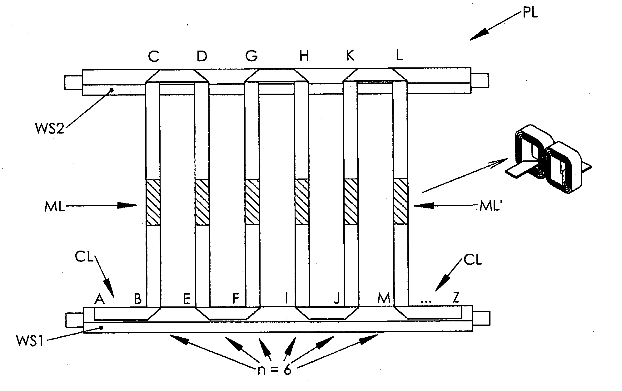
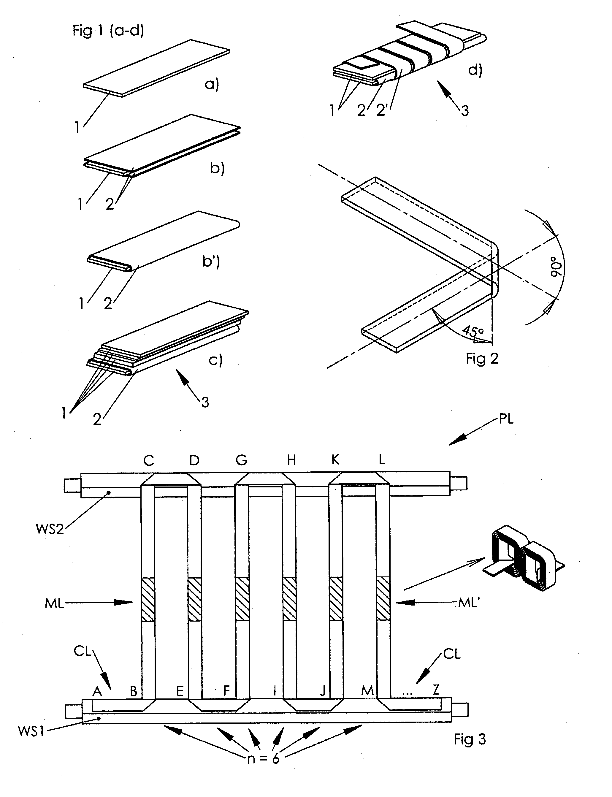
[0005]This invention describes windings, especially motor windings, which are made out of groups of coils wound with rectangular cross-section conductors, all of these coils having been made out of a suitably plied single continuous predefined length AZ (FIG. 3) of a rectangular cross-section ribbon conductor (1) or several ribbon conductors piled together in a stack (3), s. also FIG. 1. This invention shows how a stack (3) made out of a plurality of thin ribbons (1) must be folded and handled in order to benefit from the fact that a plurality of thin conductors can be much more easily bent round sharp corners than a thick conductor having the same cross section. This is a major advantage of the groups of coils as described in this invention.
[0006]Piled conductors may be also favourable at higher frequencies because of the skin effect, which is reduced even if the piled conductors are only slightly insulated by thin oxide layers, (“litz-wire”-effect).
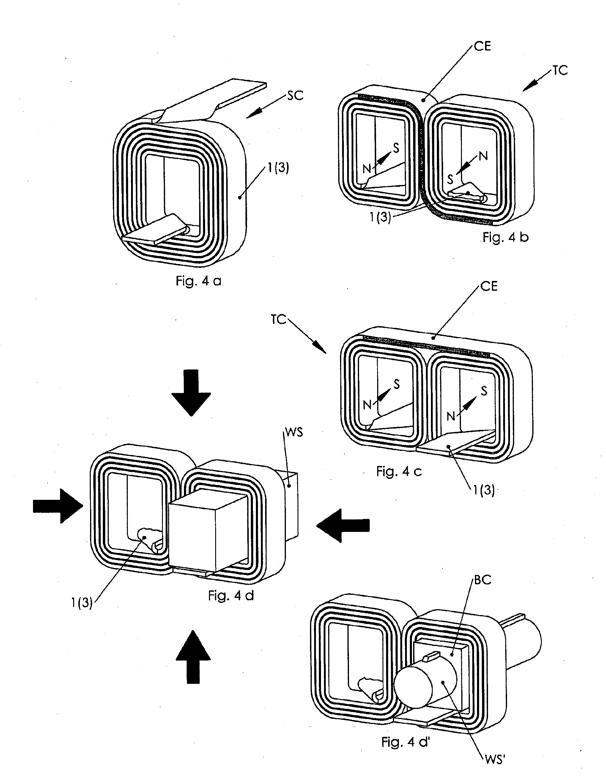
[0012]These crossovers, being specially folded as per this invention, permit the spatial, three dimensional placement of single coils SC or twin coils TC which can be inserted onto magnetic yokes MY, so that a desired polarity will result at the pole pieces PP of said magnetic yokes.

Problems solved by technology

A major problem with such coils manufactured according to the state of the art is that they can only be satisfactorily realised with thicker conductors, making them more suitable for bigger machines.
One of the biggest problems of manufacturing motors or generators with such rectangular section conductors is the special winding technique required, because the rectangular cross-section conductors have preferential bending directions and can only be processed on special machines.
Another problem of such groups of coils with non-round conductors when manufactured according to the state of the art is that several individual coils have to be connected together to realise the complex windings (e.g. phase windings) of an electrical machine.
The interconnections (crossovers) between the single coils are often difficult to realise and these can reduce the reliability, performance and cost-effectiveness of the electrical machine.

Method used


Image

  • Method for producing group of electrical coils
  • Method for producing group of electrical coils
  • Method for producing group of electrical coils

Examples


Embodiment Construction

[0025]In order to better understand the invention we will begin with the conductor ribbon 1 and the conductor ribbon stacks 3 which are preferably used when implementing this invention.

[0026]All of the groups of coils described in this invention can be made with a single or multiple current paths. This means that by winding a conductor ribbon stack 3 (such as that shown in FIG. 1c) it is possible to have a coil or group of coils with one or more internal current paths, which result from the galvanic separation of the single conductor ribbons 1 or of groups of several conductor ribbons 1 by means of an insulating tape 2, for example. A preferred winding with two current paths according to the invention is designated a bifilar winding.

[0027]FIG. 1a represents a single, non-insulated rectangular cross-section conductor ribbon 1 of undefined length which is, for example, cut out of a thin metal sheet and which can have, for example, a thickness h of down to 0.02 mm and a suitable width ...


PUM

PropertyMeasurementUnit
Lengthaaaaaaaaaa

Abstract

A method for producing a group of electrical coils for electromagnetic applications includes providing at least one piece of a continuous ribbon conductor or a ribbon conductor stack of a predefined single length. The ribbon conductor is parted in a number n of linear conductor portions. The conductor portions are place in parallel to each other prior to winding. Thereafter the conductor portions are wound in order to create a group of coils composed of a corresponding number n of coils whereby the coils are connected with each other and are made of the same piece of continuous ribbon conductor or ribbon conductor stack.

Description

CROSS-REFERENCE TO RELATED APPLICATIONS[0001]This application is a continuation of International Application No. PCT / EP2010 / 001869, filed Mar. 25, 2010, designating the United States and claiming priority to European Application No. EP 09006561.6 filed May 15, 2009.BACKGROUND OF THE INVENTION[0002]This invention relates to groups of at least two electrical coils, such as those which are used in electrical motors, generators and electromagnets, made out of conductors which are not round wires. The coils according to this invention are realised with conductors of rectangular cross-section in order to achieve superior fill factors. Such groups of coils or windings are well known from the state of the art and are most often realised with rectangular cross-section conductors. These are in most cases made out of copper and typically insulated with materials such as wire enamel.[0003]A major problem with such coils manufactured according to the state of the art is that they can only be sat...

Claims


Application Information

Patent Timeline
IPC IPC(8): H02K15/00
CPCH01F27/2847H01F41/0604Y10T29/49009H02K3/18H02K15/045H01F2017/046H01F41/061
Inventor LUNGU, CORNELIUS
Owner ELECTRIC DRIVE TECH
Learn More