

Electro-Optical Panel
- Summary
- Abstract
- Description
- Claims
- Application Information
AI Technical Summary
Benefits of technology
Problems solved by technology
Method used
Image

Examples
first embodiment
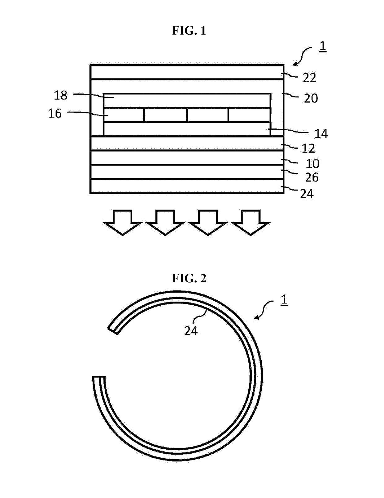
[0038]FIG. 1 is a cross-sectional view showing an organic light emitting diode display panel according to the present disclosure.
[0039]In FIG. 1, an organic light emitting diode (OLED) display panel 1 includes a flexible substrate (flexible film) 10 and a barrier layer (barrier film) 12. The flexible substrate 10 may include a polymeric material, for example, polyimide, and the barrier layer 12 may include a polymeric material or an inorganic material.
[0040]A thin film transistor (TFT) layer 14, a color filter layer 16 and an OLED layer 18 are formed on the barrier layer 12. Although not shown, the TFT layer may include a plurality of TFTs and an interlayer insulating layer covering the plurality of TFTs. In addition, the color filter layer 16 may include a color filter and a conductive line connecting the TFT and an electrode of the OLED layer 18 through the interlayer insulating layer. The OLED layer 18 may include a plurality of layers such as an anode, a cathode and an emitting ...
second embodiment
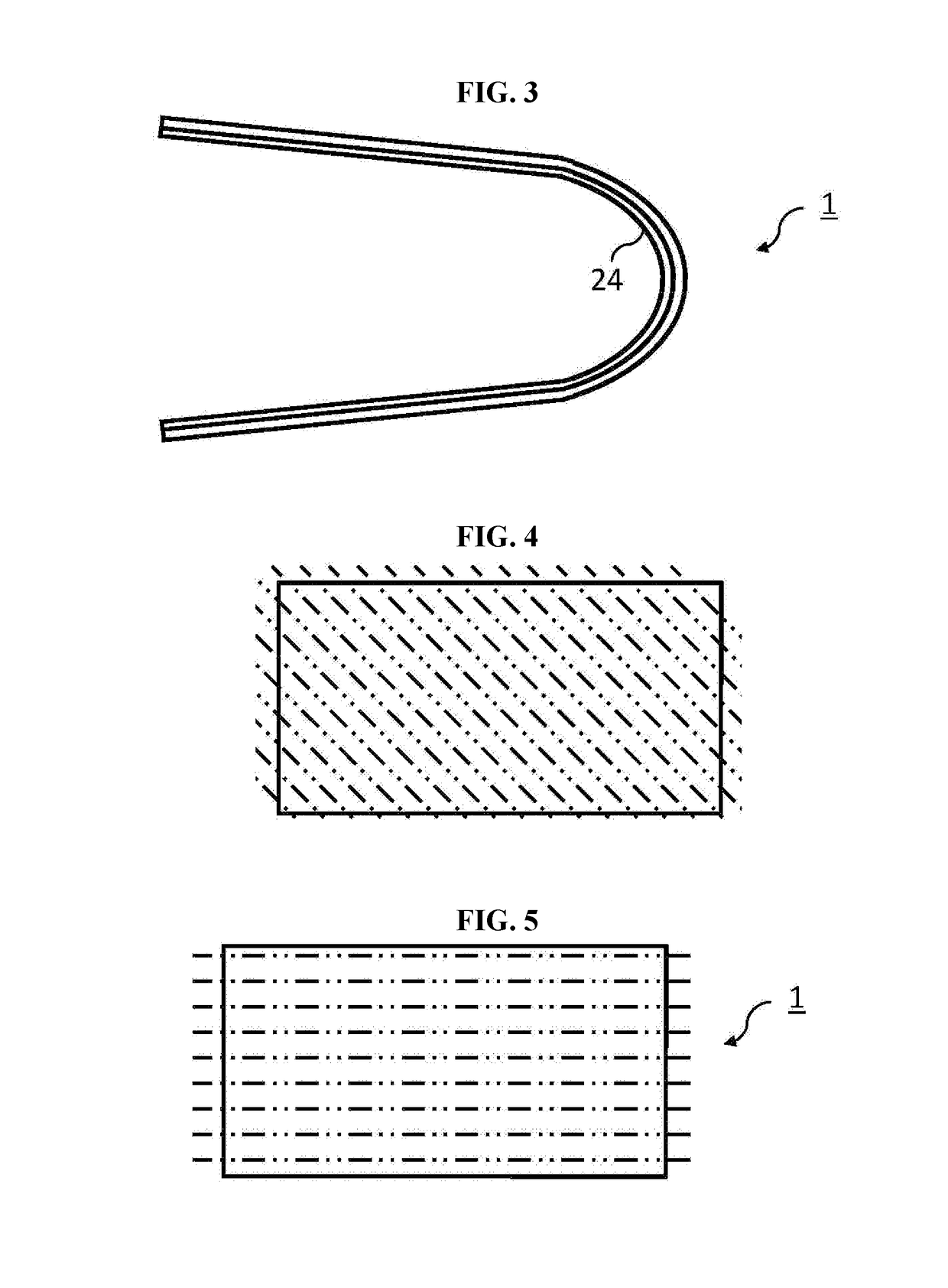
[0049]FIG. 6 is a plan view showing a main stretching axis of a front film (a stretch film) of an organic light emitting diode display panel of a rectangular shape in a flat state according to the present disclosure.
[0050]In FIG. 6, a main stretching axis direction of the stretch film of the OLED display panel may be parallel to a short axis direction of the OLED display panel.
[0051]As shown in FIG. 5, the main stretching axis direction of the stretch film may be disposed to be parallel to the long axis direction of the OLED display panel 1 so that the OLED display panel 1 can easily return to an original flat state even when the OLED display panel 1 is left in a transformed state.
[0052]FIG. 7 is a view showing organic light emitting diode display panels where long and short axes are bent.
[0053]In FIG. 7, when the OLED display panel 1 is bent or rolled, users may usually bend or roll the long axis of the OLED display panel. For example, most of users may bend or roll the long axis a...
third embodiment
[0076]FIG. 16 is a cross-sectional view showing an organic light emitting diode display panel according to the present disclosure.
[0077]In FIG. 16, an organic light emitting diode (OLED) display panel 41 having a bottom emission type further includes a retardation film 42 and a polarizing film 44. For reducing reflection of an external light, the retardation film 42 is disposed closer to a light emitting surface than a flexible substrate 10, and the polarizing film 44 is disposed closer to the light emitting surface than the retardation film 42. The retardation film 42 and the polarizing film 44 are a stretch film of a polymeric material. The retardation film 42 is attached to the flexible substrate 10 through an adhesive 26, and the polarizing film 44 is attached to the retardation film 42 through an adhesive 26. In another embodiment, the retardation film 42 may be attached directly to the flexible substrate 10 by an interaction of a covalent bond between materials of the retardat...
PUM
 Abstract
Description
Claims
Application Information