Illumination Device of a Motor Vehicle

Inactive Publication Date: 2015-01-01
DAIMLER AG
View PDF9 Cites 4 Cited by
  • Summary
  • Abstract
  • Description
  • Claims
  • Application Information

AI Technical Summary

Benefits of technology

[0022]In a further preferred embodiment, the optical component is a second reflector having a coating that reduces the light output. This

Problems solved by technology

Light-emitting diodes with several LED chips have the property that these can malfunction both with the occurrence of a so-called open load (i.e, due to interruption of the electrical circuit) and also in the

Method used


Image

  • Illumination Device of a Motor Vehicle
  • Illumination Device of a Motor Vehicle
  • Illumination Device of a Motor Vehicle

Examples


Embodiment Construction

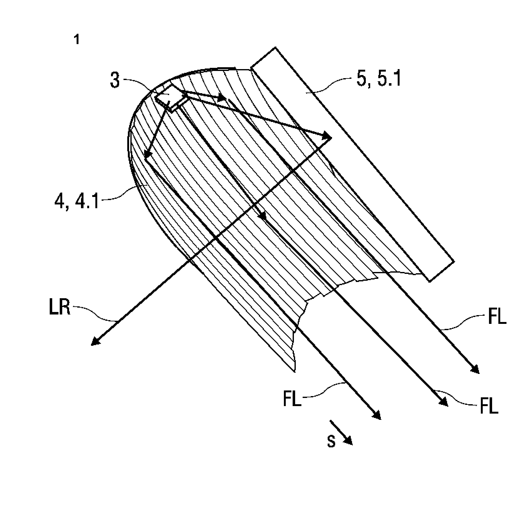
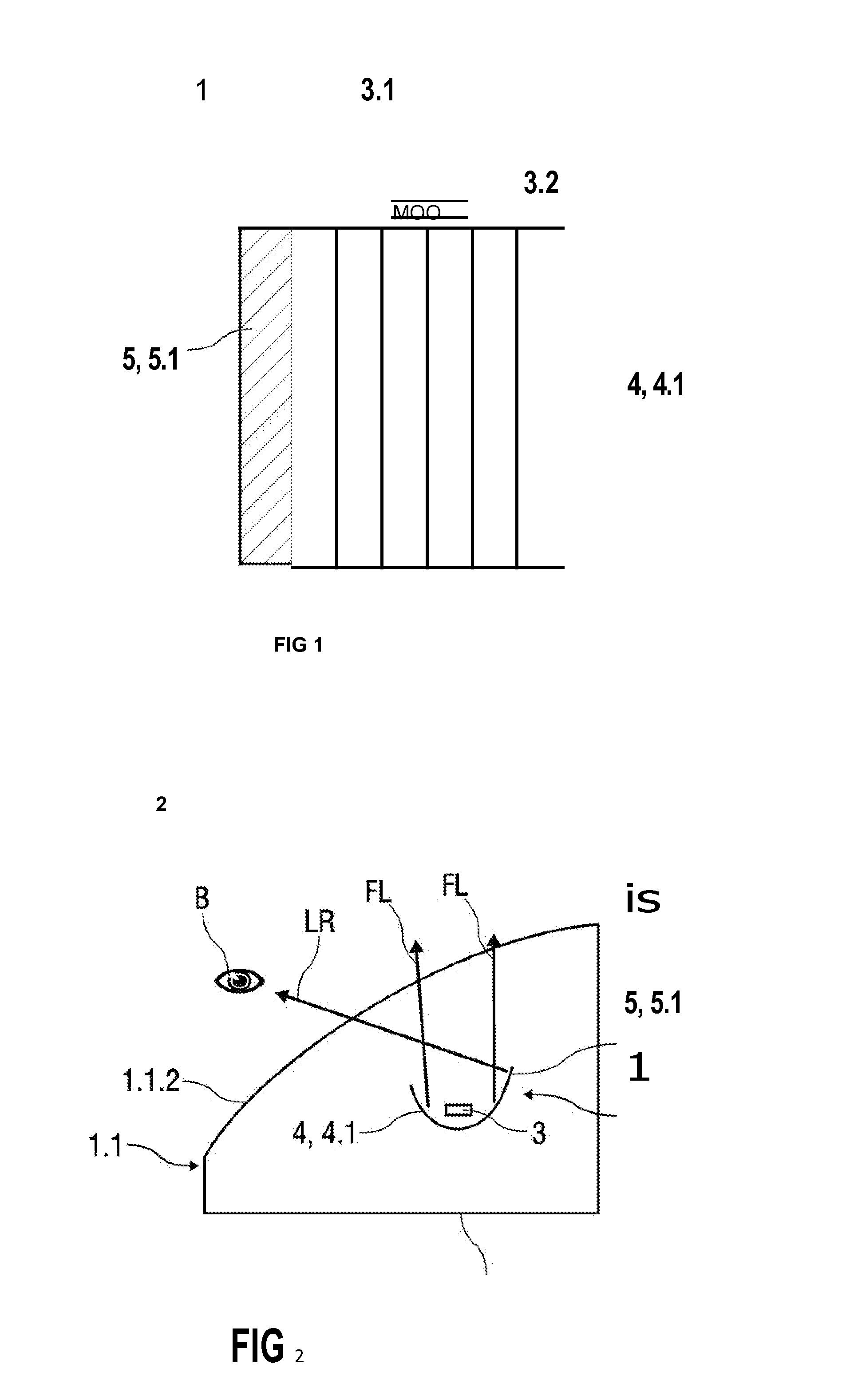
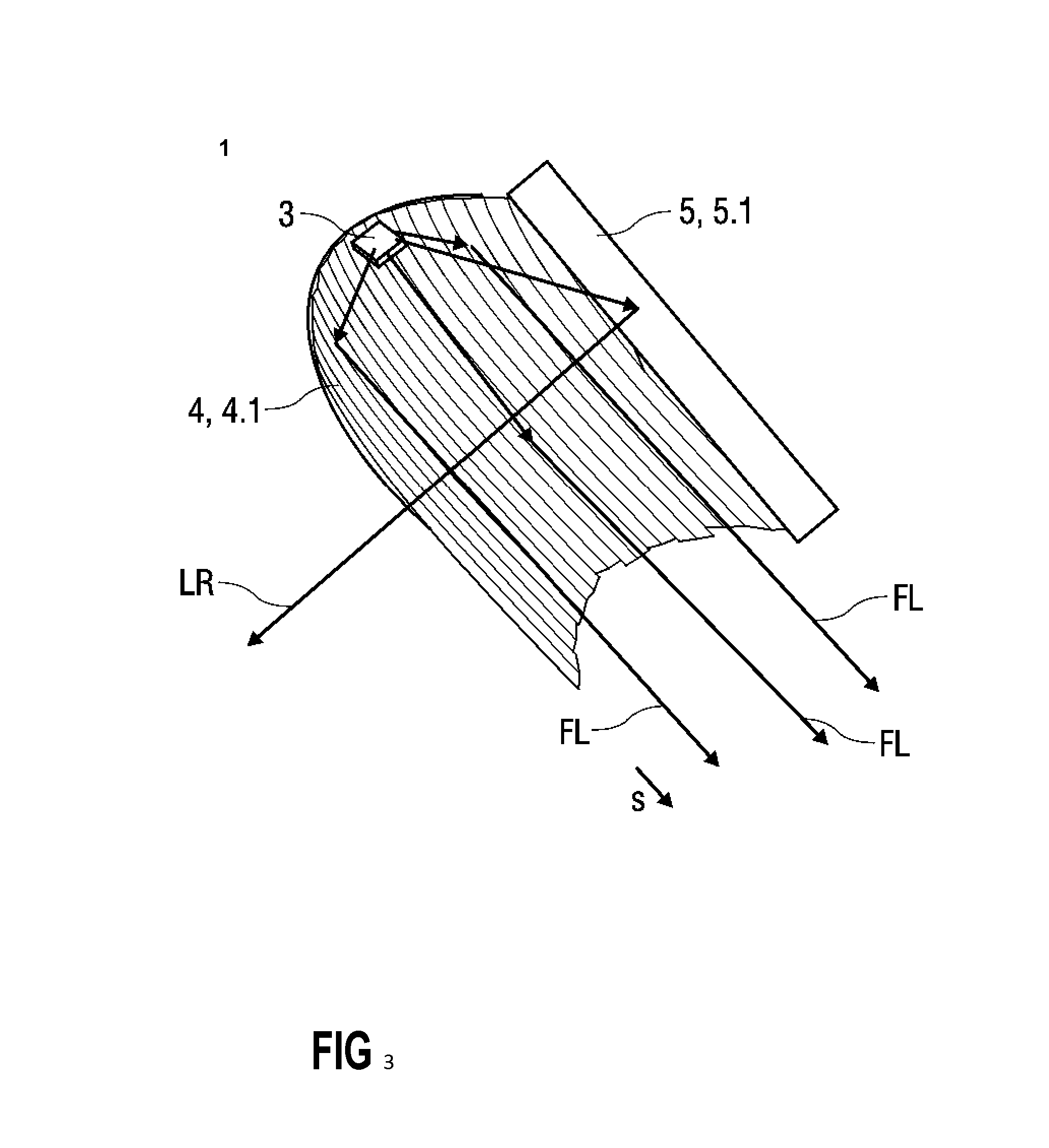
[0030]FIGS. 1 to 3 show a lamp module 1 of an illumination device 2 for a motor vehicle that is not depicted in more detail here, wherein the lamp module 1 is formed from a light source unit 3, a first optical component 4 and a second optical component 5. Therein, FIG. 1 shows a schematic and FIG. 3 shows a perspective top view of the lamp module 1 and FIG. 2 shows a schematic top view of the illumination device 2.

[0031]The lamp module 1 generates a running light distribution FL for a motor vehicle, such as, for example, dipped light, full beam light, fog light, static or dynamic cornering light, country road light, motorway light, city light, rain or snow light, daytime running light, parking light, side marker light and / or position light.

[0032]For this purpose, the lamp module 1 is integrated into the illumination device 2, which, in the sense of the invention, is embodied as a vehicle headlight, referred to below as a vehicle headlight 1.1.

[0033]Motor vehicles conventionally comp...


PUM


Abstract

An illumination device of a motor vehicle has a lamp module formed from at least one light source unit, which includes at least one light source that emits a light radiation to generate a running light distribution. An optical component deflects a part of the emitted light radiation in such a way that a depiction of the at least one light source unit is able to be generated outside of the running light distribution.

Description

BACKGROUND AND SUMMARY OF THE INVENTION[0001]Exemplary embodiments of the invention relate to an illumination device of a motor vehicle.[0002]Known illumination devices for motor vehicles can be used, among other things, as indicators, brake lights, dipped lights, rear lights, daytime running lights, front headlights etc. Therein, in particular, illumination devices having light-emitting diodes (LED), for example so-called LED headlights, are used more and more frequently, wherein conventionally there is differentiation between so-called resolved and unresolved vehicle headlights. In the case of resolved vehicle headlights, light-emitting diodes are used which comprise several light sources, wherein each of the light sources has an optical system, for example a lens or reflector. Thus, each light source contributes individually to the generation of a running light distribution of the motor vehicle. A conventional number of light sources for resolved vehicle headlights lies between f...

Claims


Application Information

Patent Timeline
IPC IPC(8): F21S8/10
CPCF21S48/1394F21S48/1388F21S48/1382F21S48/137B60Q11/005F21S41/176F21S41/336F21S41/338F21S41/37F21S41/36
Inventor BONY, ALEXIS
Owner DAIMLER AG
Why Eureka
Try Eureka