Light-emitting apparatus and vehicle headlamp system

a technology of light-emitting apparatus and headlamp system, which is applied in the direction of lighting and heating apparatus, lighting support devices, light source combinations, etc., can solve the problems of driver and others' discomfort, and achieve the effect of reducing the visual light movement and alleviating the discomfort of the driver

Inactive Publication Date: 2015-01-01
STANLEY ELECTRIC CO LTD
View PDF3 Cites 5 Cited by
  • Summary
  • Abstract
  • Description
  • Claims
  • Application Information

AI Technical Summary

Benefits of technology

[0015]According to the above-stated configuration, there is a decrease in the visual light movement when the light distribution areas near the center area in front of the subject vehicle where the viewing frequency of the driver and others is relatively high are switched, making it possible to alleviate the sense of discomfort of the driver and others.

Problems solved by technology

When driving a vehicle at night, a driver basically checks the area in front of the vehicle by irradiating a high beam from the headlamps, switching to a low beam as necessary, but also often uses the low beam due to the hassle of switching as well as the road environment.
As a result, when the light distribution areas to be turned on are switched in accordance with a change in the position of the forward vehicle, the movement of the light is not always visually smooth, causing a sense of discomfort in the driver and others.

Method used


Image

  • Light-emitting apparatus and vehicle headlamp system
  • Light-emitting apparatus and vehicle headlamp system
  • Light-emitting apparatus and vehicle headlamp system

Examples


Embodiment Construction

[0023]Now, an embodiment of the present invention will be described below with reference to the accompanying drawings.

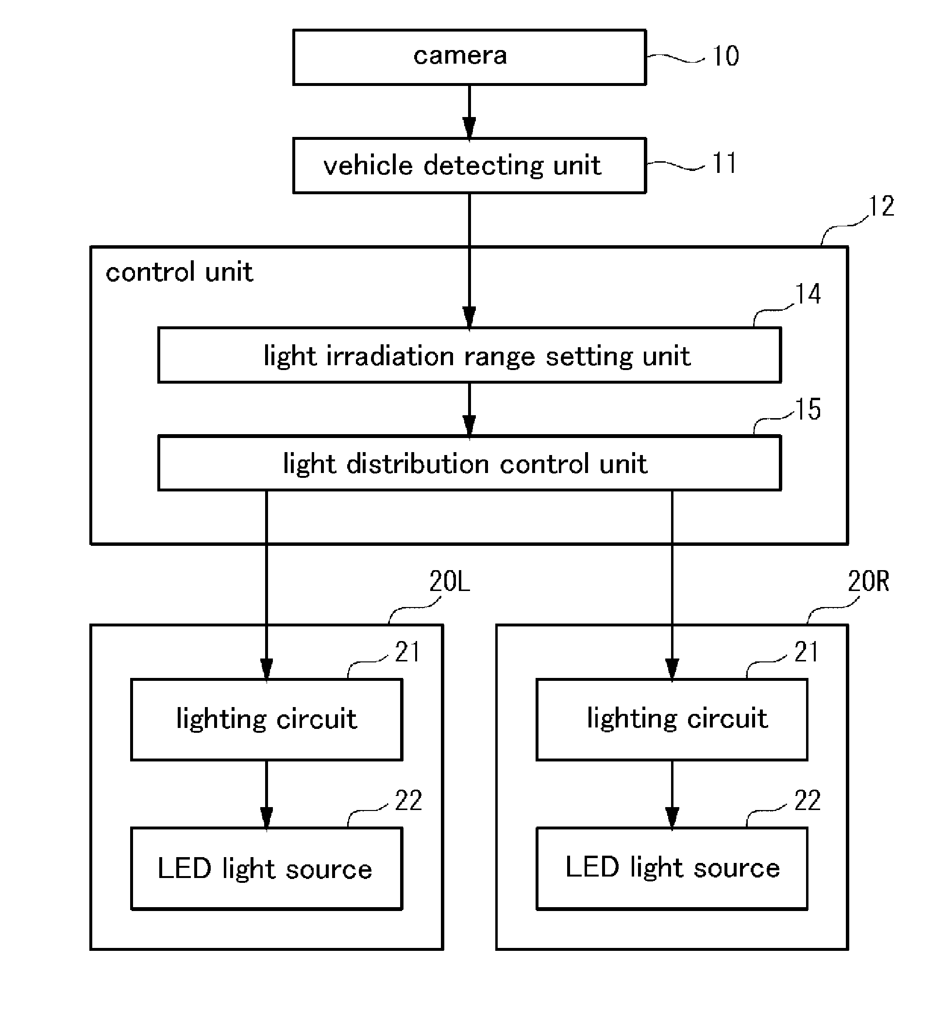
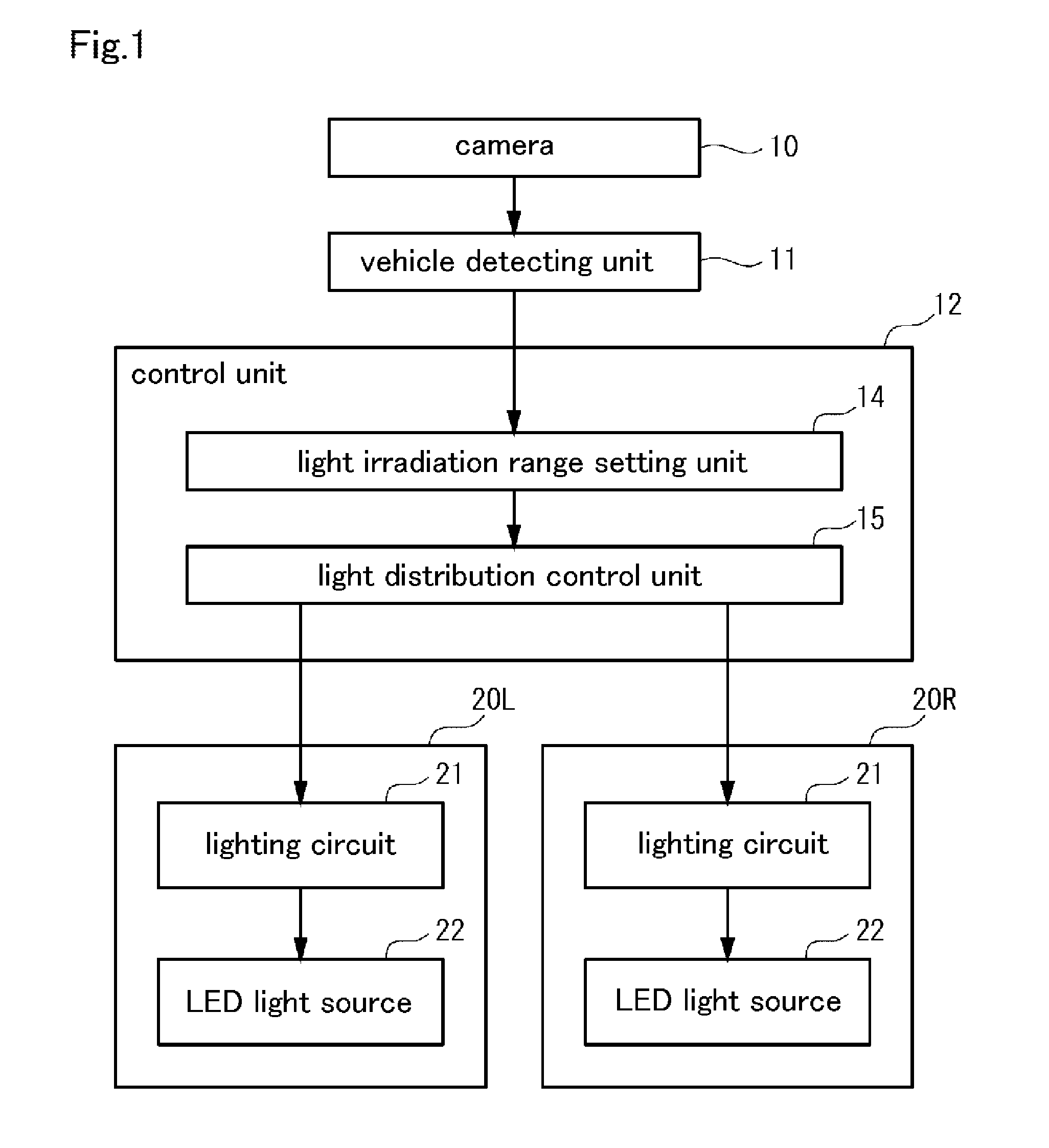
[0024]FIG. 1 is a block diagram showing the configuration of a vehicle headlamp system of an embodiment. The vehicle headlamp system shown in FIG. 1 sets a light distribution pattern based on an image obtained by taking an image of the space in front of the subject vehicle (target space) and irradiates light, and is configured to include a camera 10, a vehicle detecting unit 11, a control unit 12, and a pair of lamp units (vehicle lamps) 20R and 20L.

[0025]The camera 10 is installed in a predetermined position of the subject vehicle (near the inner rearview mirror, for example), takes an image of the space in front of the vehicle, and outputs the image (image data).

[0026]The vehicle detecting unit 11 detects the position of the forward vehicle by performing predetermined image processing using the image data output from the camera 10, and outputs the position informat...


PUM


Abstract

To provide a technique capable of alleviating the sense of visual discomfort when light distribution areas are switched. A vehicle lamp configured to include a light source, wherein the light source comprises a plurality of light-emitting units respectively comprising a control terminal for controlling light emission and extinction, arranged along a first direction, and the plurality of light-emitting units increases in a width of a first direction in proportion to a distance away from a predetermined reference position toward both sides along the first direction, with the width of a light-emitting unit corresponding to the predetermined reference position being the smallest.

Description

BACKGROUND OF THE INVENTION[0001]1. Field of the Invention[0002]The present invention relates to a technique for controlling the state of irradiation from a vehicle headlamp.[0003]2. Description of the Background Art[0004]When driving a vehicle at night, a driver basically checks the area in front of the vehicle by irradiating a high beam from the headlamps, switching to a low beam as necessary, but also often uses the low beam due to the hassle of switching as well as the road environment. Hence, light is irradiated on the upper side above a so-called cutoff line, possibly casting glare onto an oncoming vehicle or preceding vehicle (hereinafter referred to as “forward vehicle”). Thus, as disclosed in Japanese Patent No. 4624257 for example, in recent years there have been proposed various light distribution control techniques for detecting the position of the lamps (tail lamps or headlamps) of the forward vehicle using an image obtained by taking an image of the forward vehicle by ...

Claims


Application Information

Patent Timeline
Patent Type & Authority Applications(United States)
IPC IPC(8): F21V23/00F21S8/10
CPCF21V23/003F21S48/10B60Q1/143F21S48/1154B60Q2300/41H01L33/32B60Q2300/42F21S48/1747H01L33/387F21Y2103/10F21Y2113/20F21Y2115/10F21S41/143F21S41/151F21S41/663
Inventor LIANG, JI-HAOKOIKE, TERUO
Owner STANLEY ELECTRIC CO LTD
Why Eureka
Try Eureka