Hydraulic unit

Active Publication Date: 2015-01-01
CONTINENTAL TEVES AG & CO OHG
View PDF14 Cites 2 Cited by
  • Summary
  • Abstract
  • Description
  • Claims
  • Application Information

AI Technical Summary

Benefits of technology

[0004]An aspect of the present invention now consists in specifying a hydraulic unit which allows particularly efficient fastening of the motor housing to the pump housing by means that are as sim

Problems solved by technology

The need to use threaded bushings and the fixing of the threaded bushing in th

Method used


Image

  • Hydraulic unit
  • Hydraulic unit

Examples


Embodiment Construction

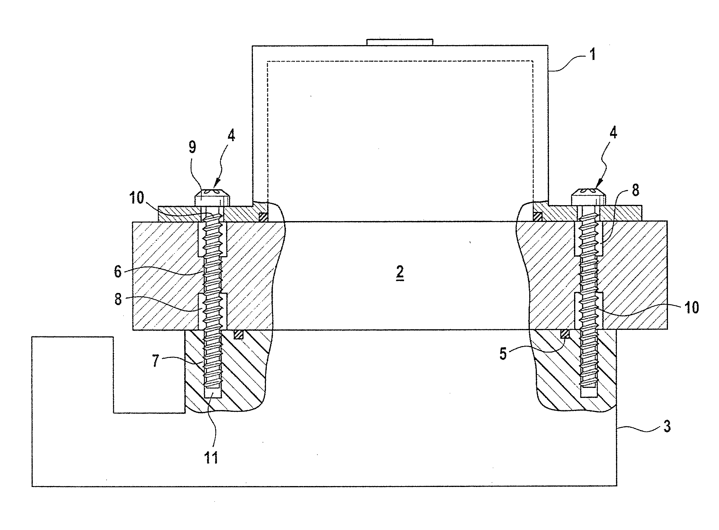
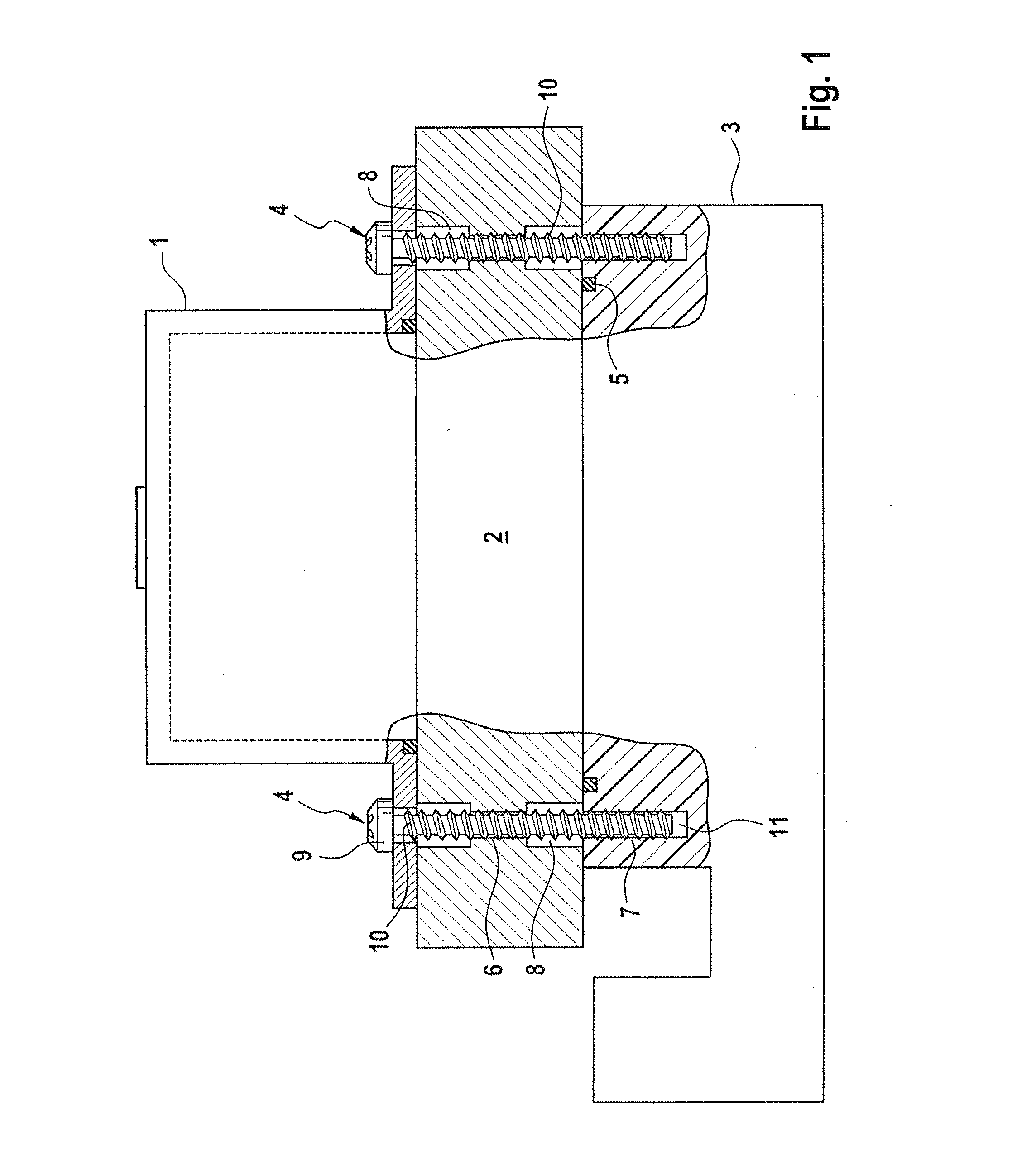
[0008]In a schematic representation, FIG. 1 shows a hydraulic unit consisting of a motor housing 1 for accommodating components of an electric motor and having a pump housing 2 for accommodating components of a pump, which is driven by the electric motor in order to pump pressure medium, having a respective through hole arranged in the pump housing 2 on each side of the motor housing 1 for fastening the motor housing 1 on the pump housing 2 by means of two screws 4, and having a control device 3, which is arranged on the opposite flange side of the pump housing 2 from the motor housing 1.

[0009]For efficient fastening of the subassemblies described, the invention envisages that a retaining region 6 for the associated screw 4 is provided in each case in one of the two through holes 8 in the pump housing 2, for which purpose an internal thread is produced in the retaining region 6 directly by the thread of the screw 4 during the process of screwing in the screw, said thread preferably ...


PUM


Abstract

The invention relates to a hydraulic unit including a motor housing for receiving components of an electric motor; having a pump housing for receiving components of a pump, which is driven in order to pump a pressure medium from the electric motor, the pump housing having at least one through-bore for fixing the motor housing to the pump housing by a screw; and having a control device which is arranged on the pump housing face opposite the motor housing. A retaining region for the screw is provided in the through-bore of the pump housing for the purpose of an efficient attachment, the retaining region having an inner thread which is cut or tapped into the retaining region by the thread of the screw during the screw-in process.

Description

CROSS REFERENCE TO RELATED APPLICATIONS[0001]This application is the U.S. National Phase Application of PCT / EP2012 / 074773, filed Dec. 7, 2012, which claims priority to German Patent Application Nos. 10 2012 200 318.5, filed Jan. 11, 2012 and 10 2012 204 526.0, filed Mar. 21, 2012, the contents of such applications being incorporated by reference herein.FIELD OF THE INVENTION[0002]The invention relates to a hydraulic unit having a motor housing for accommodating components of an electric motor and having a pump housing for accommodating components of a pump, which is driven by the electric motor in order to pump a pressure medium, having at least one through hole in the pump housing for fastening the motor housing on the pump housing by a screw, and having a control device, which is arranged on the opposite side of the pump housing from the motor housing.BACKGROUND OF THE INVENTION[0003]EP 0 975 500 B1, which is incorporated by reference, describes a hydraulic unit having a motor hou...

Claims


Application Information

Patent Timeline
IPC IPC(8): F04D29/60
CPCF04D29/605B60T8/368F04B53/22F16B37/005F16B25/0031
Inventor HEISE, ANDREAS
Owner CONTINENTAL TEVES AG & CO OHG
Why Eureka
Try Eureka