Sampling pipette which detects the passage of the piston through a predetermined position

a technology of sampling pipettes and pistons, which is applied in the field of sampling pipettes, can solve the problems of difficult installation, risk of failure, and the inability to detect the passage of the piston through a predetermined position, and achieve the effects of less risk of failure, easy installation, and greater reliability

Active Publication Date: 2015-01-01
GILSON SAS
View PDF3 Cites 6 Cited by
  • Summary
  • Abstract
  • Description
  • Claims
  • Application Information

AI Technical Summary

Benefits of technology

[0013]Therefore, the invention has the advantage that the piston travel length and the length of the relative displacement between the fixed and mobile contacts of the switch are no longer identical. The result is greater reliability, easier installation and a much smaller risk of failure.
[0014]As will be disclosed below, some or all of the detection means mentioned above are preferably integrated into the control button. It is easy to install them there, and this solution makes it easy to apply the invention on all existing pipettes without excessively changing the initial design. Nevertheless, the system may be installed elsewhere in the pipette, preferably at least partly in the control button, but also in other appropriate locations. For example, the switch and its control means may be located between the bottom end of the control rod and the piston.

Problems solved by technology

Thus, the long travel distance required for contacts 118 makes it difficult to install them, particularly due to the necessary presence of electrical wires 120 which must be sufficiently long to tolerate the movement between the fixed microprocessor 84 and the low point of the contacts 118.
This also introduces a risk of failure because there is a risk that electrical wires 120 can be trapped during displacements of the pipette piston.

Method used


Image

  • Sampling pipette which detects the passage of the piston through a predetermined position
  • Sampling pipette which detects the passage of the piston through a predetermined position
  • Sampling pipette which detects the passage of the piston through a predetermined position

Examples


Embodiment Construction

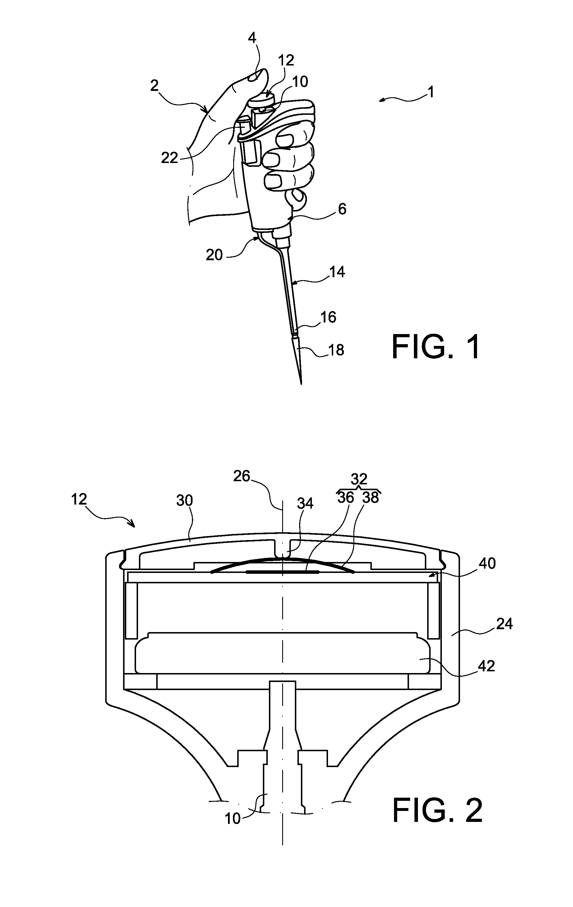
[0045]FIG. 1 shows a manually actuated sampling pipette 1 held in an operator's hand 2, the operator using his thumb 4 to actuate the pipette to dispense previously drawn in liquid.

[0046]More precisely, the pipette 1 comprises a handle 6 forming the upper body of the pipette, handle from which a control rod 10 projects carrying a control button 12 at its top end in the pipetting position, on the top part of which the operator will press with his thumb. Note that a display screen (not shown) may be provided on the handle 6.

[0047]Under the handle 6, the pipette 1 comprises a removable low part 14 that is terminated near the bottom by a cone support end piece 16 onto which a consumable 18, also called the sampling cone, fits. After pipetting, the cone may be ejected by an ejector 20 mechanically in a known manner, the actuation button 22 for the ejector is also projecting on the top of the handle, close to the control button 12.

[0048]FIG. 2 shows details of the control button 12.

[0049]...


PUM


Abstract

The invention relates to a manually actuated sampling pipette, comprising a piston designed to undergo a dispensing movement during which first elastic return means are loaded, followed by a purge movement during which second elastic return means are loaded, and comprising an electronic device (40) that will receive a switching signal notifying passage of the piston through a predetermined position along its dispensing distance or its purge distance, position in which the elastic means have a predetermined deformation. The pipette also includes a switch (32) that outputs the signal to the electronic device. Furthermore, an elastic support (30) is capable of deforming under the effect of the axial pressure applied by the operator, and the pipette is designed such that deformation of the support, generating switching, is caused when the intensity of the axial pressure is greater than the intensity bringing the elastic means to their predetermined strain level.

Description

TECHNICAL FIELD[0001]The invention relates to the field of sampling pipettes, also called laboratory pipettes or liquid transfer pipettes, designed for sampling and dispensing liquid in containers or similar devices.[0002]Pipettes concerned by this invention are manually actuated pipettes. These pipettes are designed to be held by an operator in one hand during liquid sampling and dispensing operations, these operations being done by moving a control button by applying an axial actuation pressure on this button.[0003]More specifically, the invention relates to pipette means for detection of the piston passing through a predetermined position along its dispensing movement or its purge movement.STATE OF PRIOR ART[0004]Being able to detect the passage of the piston through a predetermined position is useful in many respects. For example, it can be used to verify a count of the number of pipetting operations made with a single pipette as disclosed in document WO01 / 76749. This document d...

Claims


Application Information

Patent Timeline
Patent Type & Authority Applications(United States)
IPC IPC(8): B01L3/02
CPCB01L3/0237B01L2300/02B01L2300/023B01L3/0217B01L2200/143
Inventor BARON, STEFEN
Owner GILSON SAS
Why Eureka
Try Eureka