

Functional uterine manipulator
a uterine manipulator and functional technology, applied in the field of uterine manipulators, can solve the problems drawbacks of current uterine manipulators, loss of pneumoperitoneum,
- Summary
- Abstract
- Description
- Claims
- Application Information
AI Technical Summary
Benefits of technology
Problems solved by technology
Method used
Image

Examples
Embodiment Construction
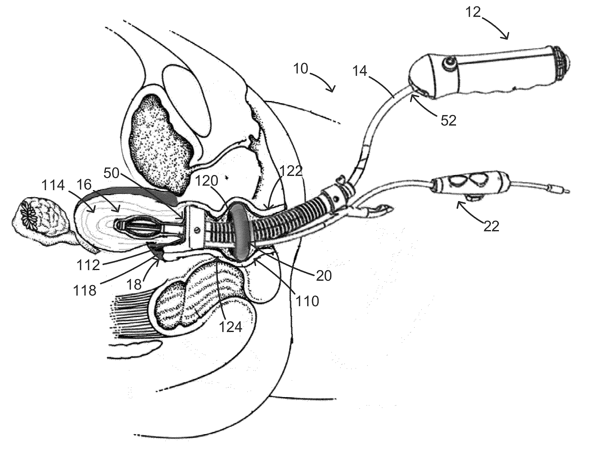
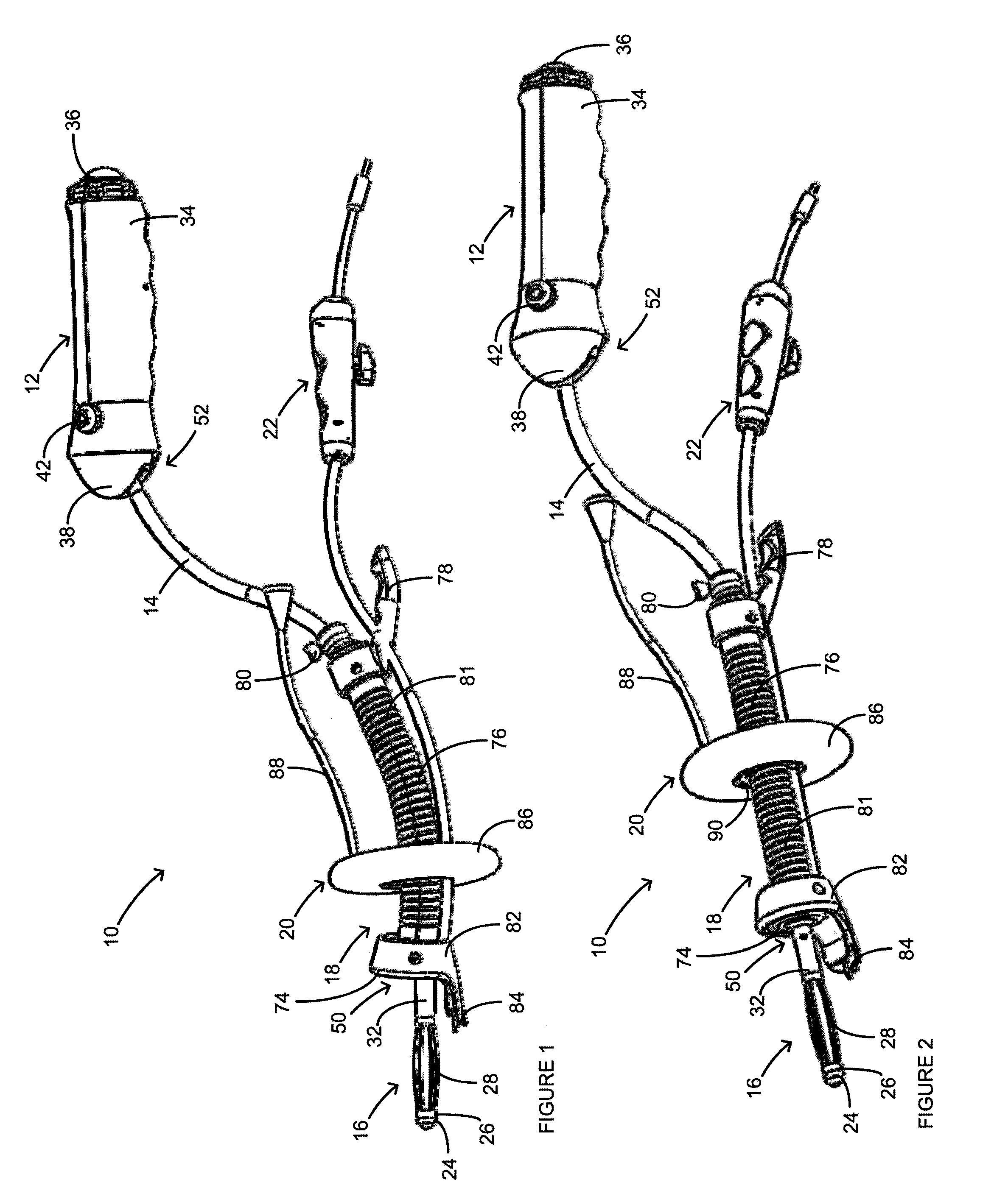
[0026]FIGS. 1 and 2 illustrate a functional uterine manipulator 10, according to the invention, for use in vaginal hysterectomies, laparoscopically assisted vaginal hysterectomies, and / or other pelvic procedures. The uterine manipulator 10 can include a handle 12, a shaft 14, a tip assembly 16, a cutting assembly 18, a pneumooccluder 20, and an electrical connector assembly 22. During use, the uterine manipulator 10 can be inserted into a patient's vagina 110, as shown in FIG. 12A, and then guided past the cervix 112 and into the uterus 114, as shown in FIG. 12B, using the handle 12. More specifically, as shown in FIGS. 12B and 12C, when the uterine manipulator 10 is inserted, the tip assembly 16 can be positioned in the uterus 114, the cutting assembly 18 can be positioned adjacent to the vaginal fornix 118 and can press against the cervix 112, and the pneumooccluder 20 can be positioned inside the vagina 110.
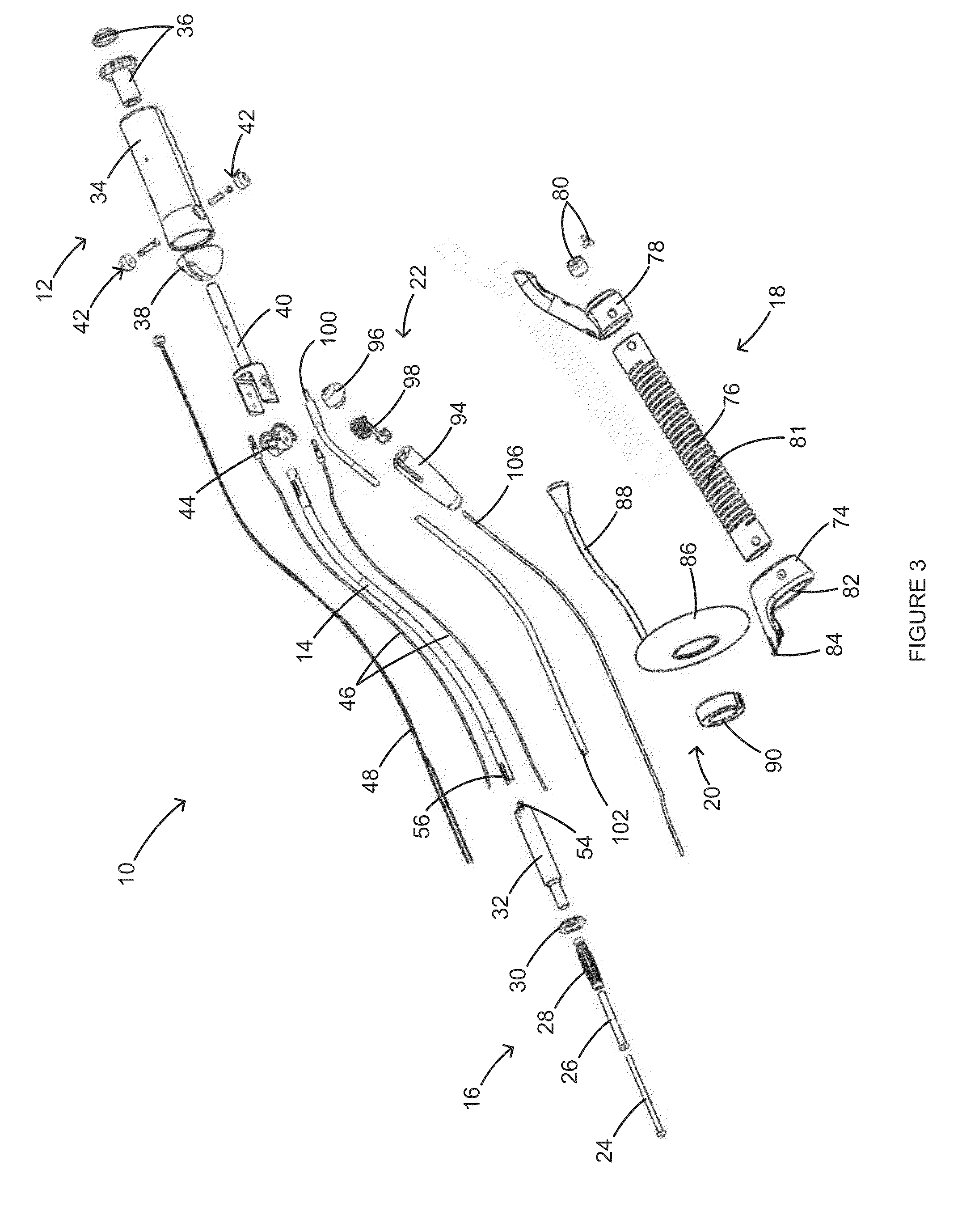
[0027]As shown in FIG. 3, the tip assembly 16 can include an expansion ti...
PUM
 Abstract
Description
Claims
Application Information