Manual thrombectomy device

a thrombus and thrombosis technology, applied in the field of thrombosis devices, can solve the problems of reducing the ability of thrombosis, difficult to remove thrombosis organized and wall-adherent, and difficult to complete removal and retrieval of thrombosis, so as to facilitate the removal of thrombosis and clean the vessel walls.

Inactive Publication Date: 2015-01-01
AHN JIYONG
View PDF2 Cites 44 Cited by
  • Summary
  • Abstract
  • Description
  • Claims
  • Application Information

AI Technical Summary

Benefits of technology

[0038]A manual thrombectomy device according to the present invention can easily detach thrombi from a blood vessel wall by manually rotating a lumen shaft right and left because a plurality of elastic wires are connected to the lumen shaft to form one or more cages longitudinally and the torque of the lumen shaft can be wholly transmitted to the elastic wires of the cages.
[0039]And because the inside of the lumen shaft is partitioned along a longitudinal direction into an aspiration lumen and an inflow lumen and a plurality of aspiration and outflow holes are formed at the opposite sides of the distal portions of the aspiration and

Problems solved by technology

The rheolytic thrombectomy catheter generally reduces the thrombectomic ability in a vessel having a large inner diameter and has the inability to remove organized and wall-adherent thrombi.
In case of the mesh or loop used to catch the thrombi and retrieve into the inside of the catheter such as Korean Patent No. 10-1303612 and U.S. Pat. No. 6,458,145, the complete removal and retrieval of the thrombi is difficult.
U.S. Pat. No. 5,766,191 is the cage-type, but has similar problems as the loop-type.
Therefore, the thrombi are inefficiently removed.
However, the high pressure tube and the fluid jet emanator have to be especially installed.
Because the high pressured fluid of the fluid jet emanator is indirectly jetted

Method used


Image

  • Manual thrombectomy device
  • Manual thrombectomy device
  • Manual thrombectomy device

Examples


Embodiment Construction

[0050]Detailed descriptions of preferred embodiments of the present invention are provided below with reference to accompanying drawings to be easily understood by those skilled in the art having ordinary knowledge in the technical field of the present invention. However, the present invention is not to be limited to the disclosed embodiments below, it is intended to be embodied to various applications based on the disclosed embodiments.

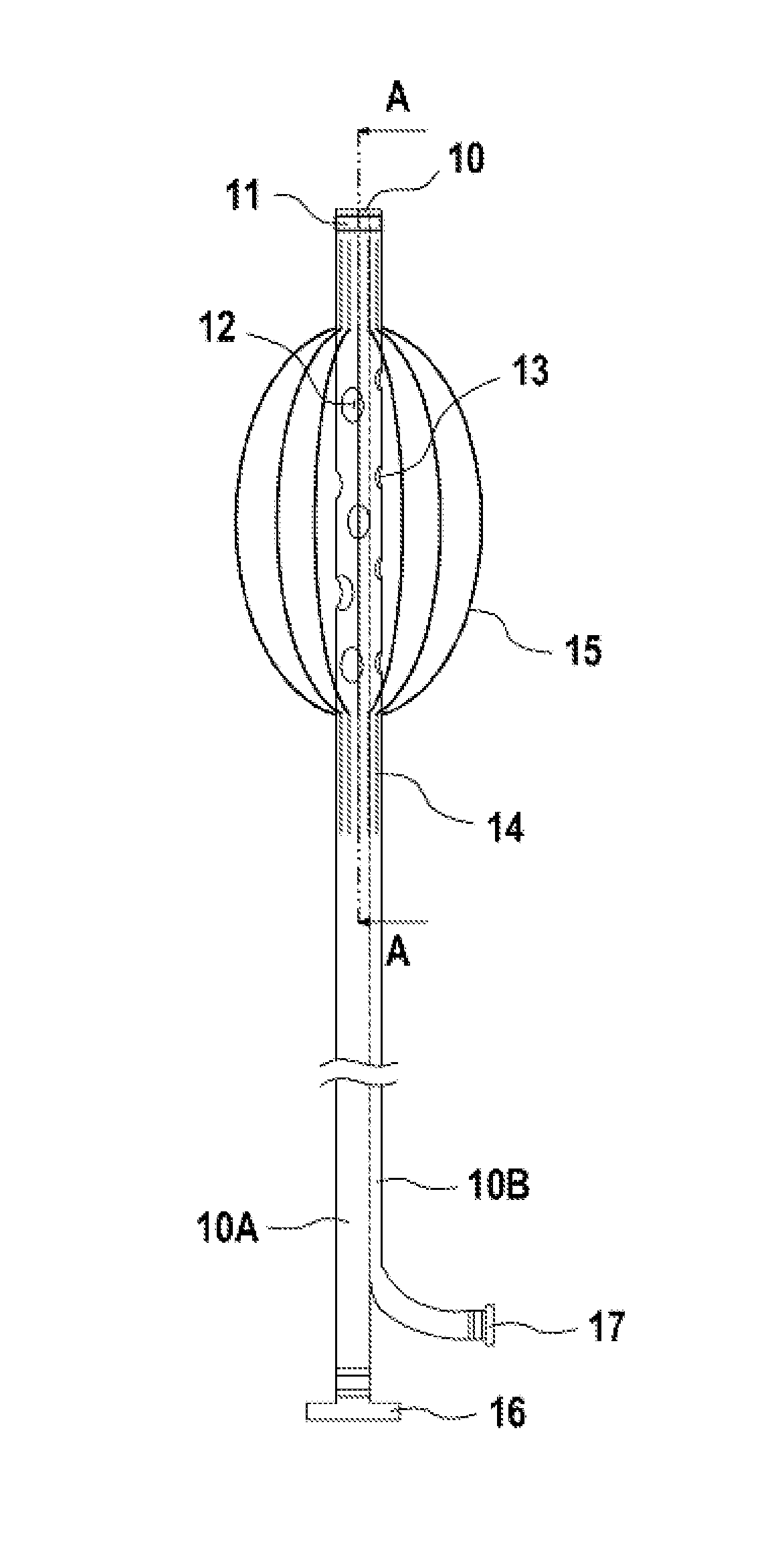
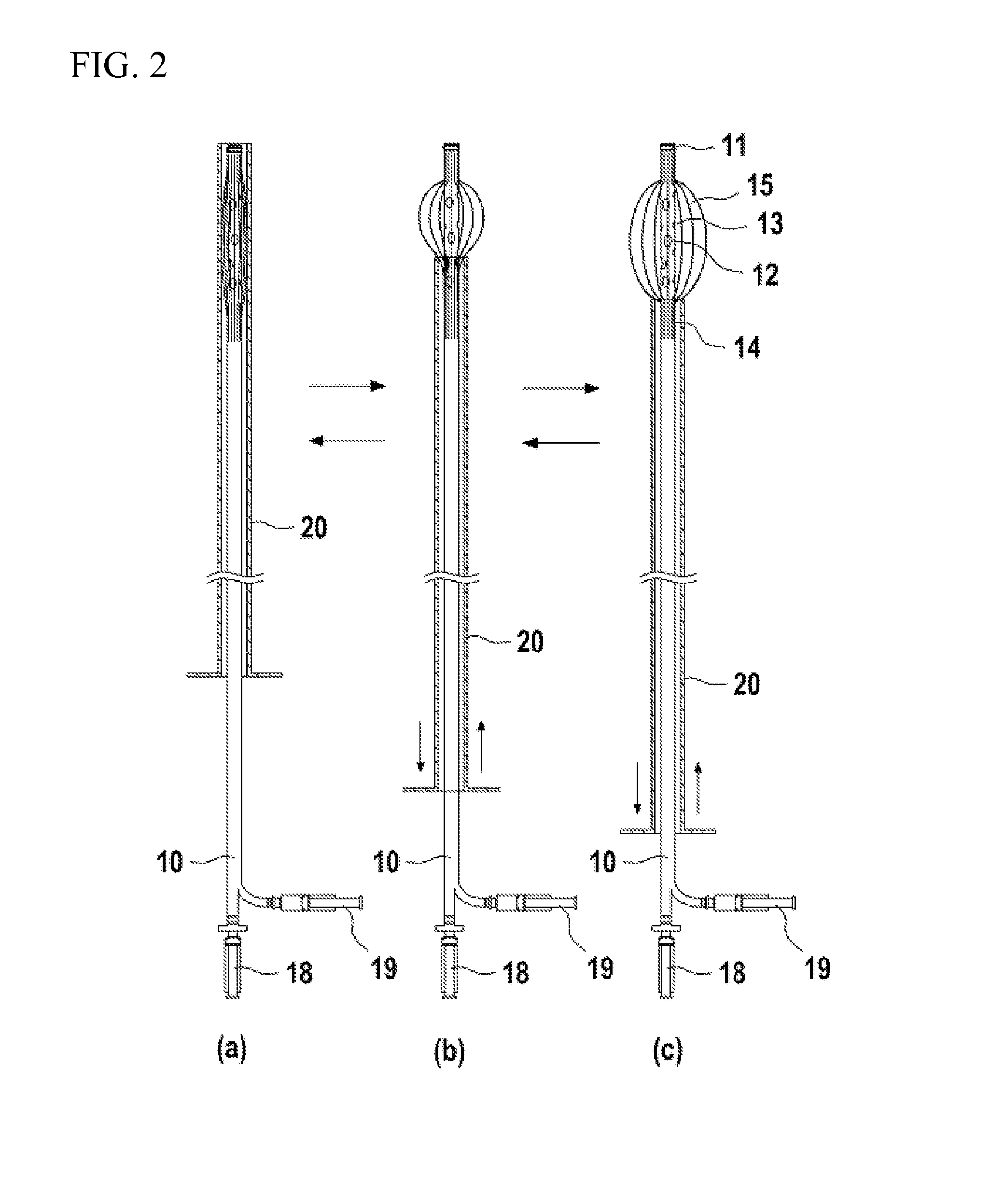
[0051]A manual thrombectomy device according to an embodiment of the present invention basically, as shown in FIGS. 1 and 2, comprises: a hollow lumen shaft 10 having a plurality of holes 12 and 13 formed to penetrate a side of a distal end portion; a plurality of elastic wires 15 connected to the distal end portion of the lumen shaft 10 in a longitudinal direction of the lumen shaft 10 to form one or more cages wrapping around the holes 12 and 13; and a sheath 20 configured to wrap around the elastic wires 15 and the lumen shaft 10 and to move back ...


PUM


Abstract

Disclosed are manual thrombectomy devices having a plurality of elastic wires to form one or more cages and/or soft brushes connected to a lumen shaft along a longitudinal direction to easily detach thrombi from a vessel wall by manually rotating the lumen shaft right and left. And without any extra inflow tube, the manual thrombectomy device has an aspiration lumen and an inflow lumen in one body of the lumen shaft not only for preventing occurrence of a vacuum or a low pressure state in the blood vessel due to the thrombi aspiration during operation, but also for cleaning the vessel wall through outflow holes and for excreting the thrombi through aspiration holes.

Description

CROSS-REFERENCE TO RELATED APPLICATION[0001]This application claims priority to U.S. Provisional Patent Application No. 61 / 841,374, filed on Jun. 30, 2013, and Korean Patent Application No. 10-2013-0166393, filed on Dec. 30, 2013, which claims priority to the former U.S. Provisional Patent Application No. 61 / 841,374, under 35 U.S.C. 119, the entire contents of which are hereby incorporated by reference.BACKGROUND OF INVENTION[0002]1. Field of the Invention[0003]The present invention relates to thrombectomy devices, and more particularly to manual thrombectomy devices for inexpensively and easily detaching, macerating and removing thrombi organized in not only native vessels, but also graft prostheses such as arterio-venous grafts (AVG) or other vessel grafts.[0004]2. Description of the Related Art[0005]Not only in native vessels of a human body, but also in graft prostheses such as arterio-venous grafts or other vessel grafts used in a blood dialyses operation and the like, blood is...

Claims


Application Information

Patent Timeline
IPC IPC(8): A61B17/3207
CPCA61B2017/320733A61B17/320725A61B17/221A61B2017/2212A61B2017/320012A61B17/22A61B17/3205A61B17/34A61M25/09
Inventor AHN, JIYONG
Owner AHN JIYONG
Why Eureka
Try Eureka