Magnetic cooling apparatus

a cooling apparatus and magnetic technology, applied in lighting and heating apparatus, machines using electric/magnetic effects, refrigerating machines, etc., can solve the problems of low energy efficiency difficult to minimize the size of magnetic cooling apparatus, and ozone layer destruction, so as to minimize the heat loss generated during the circulation of heat transfer fluid and the effect of magnetic cooling apparatus

Active Publication Date: 2015-01-08
SAMSUNG ELECTRONICS CO LTD
View PDF6 Cites 57 Cited by
  • Summary
  • Abstract
  • Description
  • Claims
  • Application Information

AI Technical Summary

Benefits of technology

[0010]It is an aspect of the present invention to provide a magnetic cooling apparatus wherein a magnetic regenerator reciprocates or rotates without an ad

Problems solved by technology

However such a refrigerant causes environmental problems, such as destruction of an ozone layer and global warming.
However, it may be difficult to minimize the size of the magnetic cooling apparatus using the motor as a power source and the magnetic cooling apparatus has low energy effi

Method used


Image

  • Magnetic cooling apparatus
  • Magnetic cooling apparatus
  • Magnetic cooling apparatus

Examples


Embodiment Construction

[0060]Reference will now be made in detail to the embodiments of the present invention, examples of which are illustrated in the accompanying drawings, wherein like reference numerals refer to like elements throughout.

[0061]Embodiments described in this specification and constructions shown in the drawings are merely preferred examples of the disclosed invention and it should be understood that there are various modifications replacing the embodiments of this specification and the drawings at the time of filing of the present application.

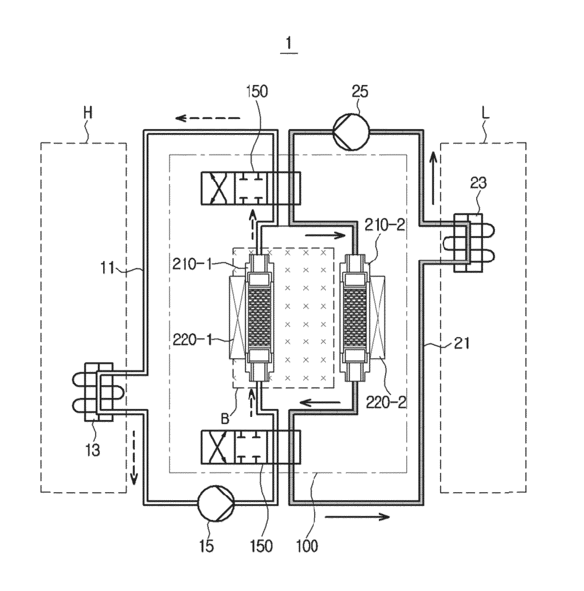
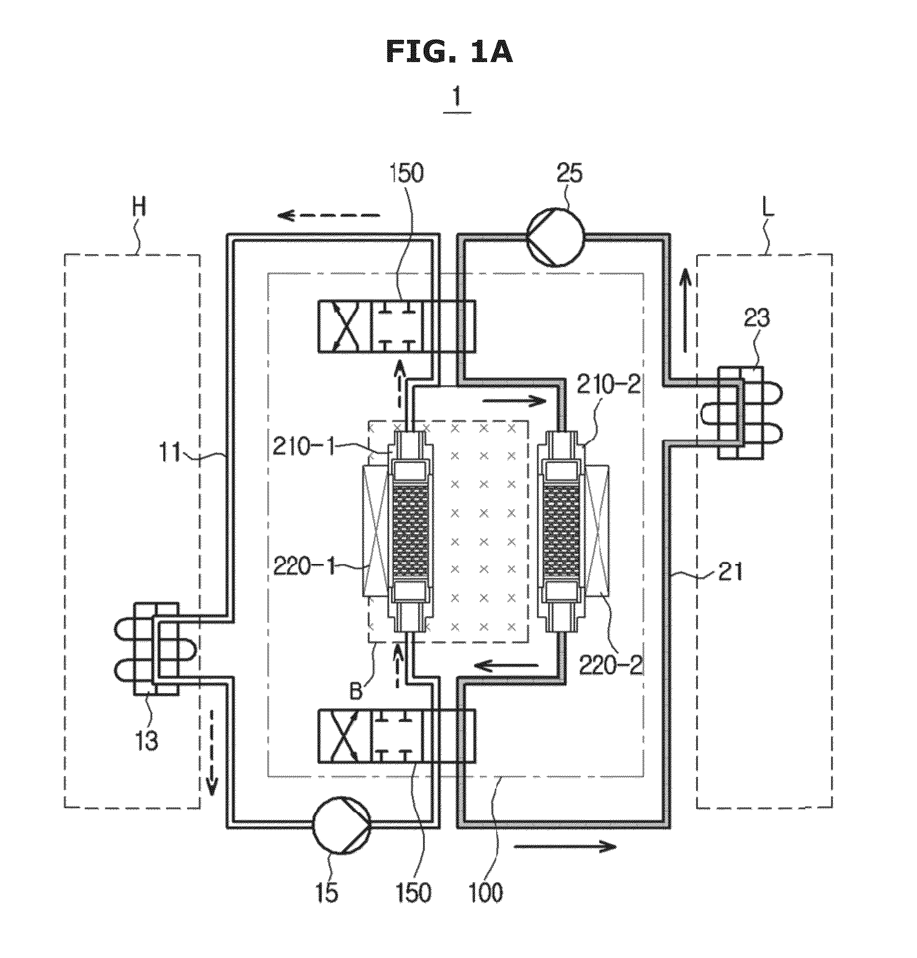
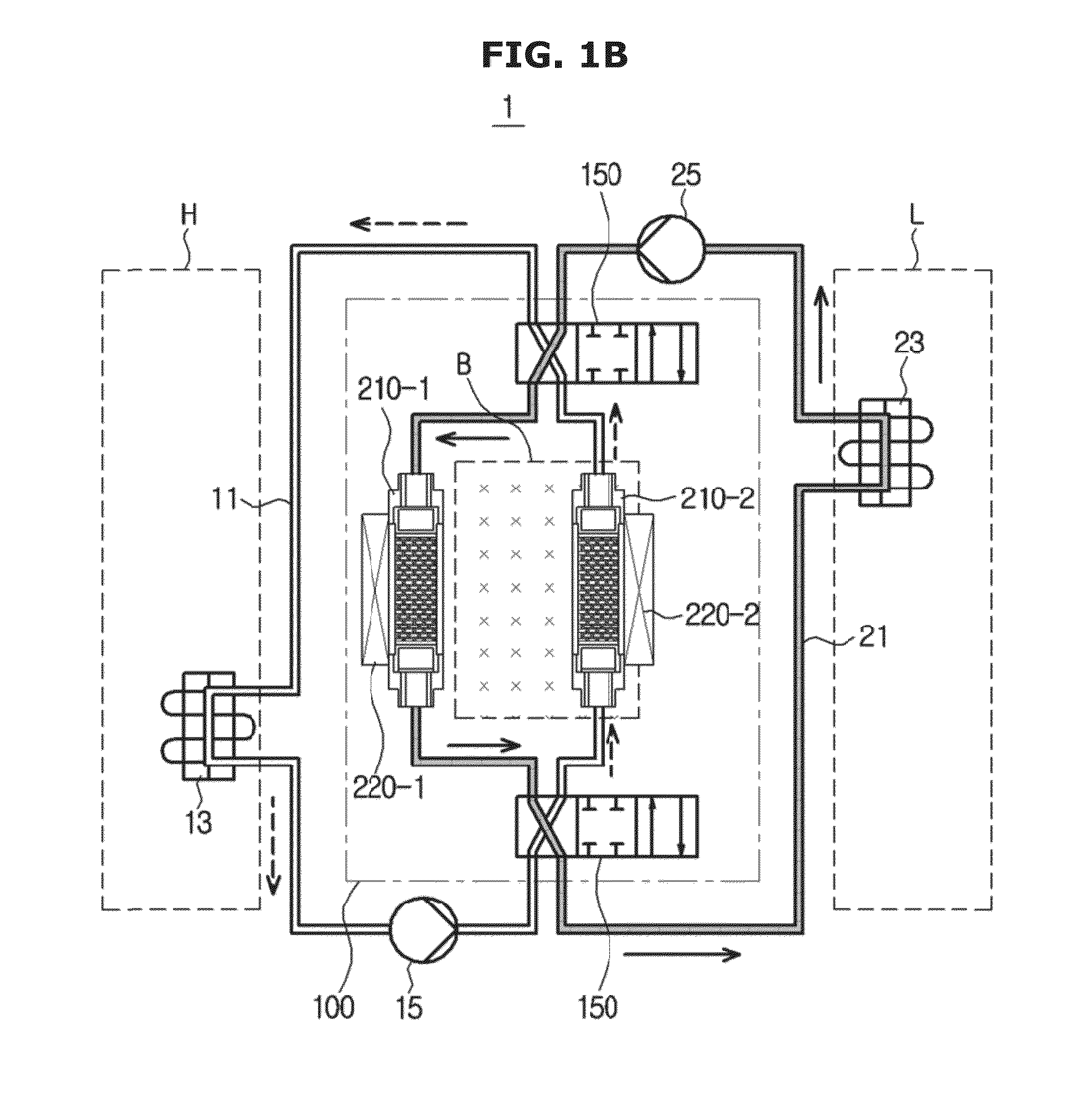
[0062]FIGS. 1a and b are views schematically showing a magnetic cooling apparatus according to an embodiment, FIG. 2 is a control block diagram of a magnetic heat exchanger according to an embodiment, FIG. 3 is a view illustrating a heat exchange cycle of the magnetic heat exchanger according to the embodiment, FIG. 4 is a view showing an example of a driving unit included in a magnetic regenerator driving device according to an embodiment, and FIG....


PUM


Abstract

A magnetic cooling apparatus including a plurality of magnetic regenerators including a plurality of magnetocaloric materials to emit heat when magnetized and to absorb heat when demagnetized. The magnetic regenerators are rotatably disposed on a circumference having a predetermined radius, at least one coil is disposed on the circumference and coupled to the magnetic regenerators, and a plurality of permanent magnets is provided inside and outside the circumference to generate a magnetic field to magnetize or demagnetize the magnetic regenerators. The at least one coil interacts with the magnetic field generated by the permanent magnets to rotate the magnetic regenerators. The coil interacting with the magnetic field to magnetize or demagnetize the magnetic regenerators is coupled to the magnetic regenerators such that the magnetic regenerators reciprocate or rotate, thereby minimizing a size of the magnetic cooling apparatus, relative to the use of a motor. In addition, a member to switch a channel of a heat transfer fluid directly performs heat transfer between the heat transfer fluid and an external fluid, thereby minimizing heat loss.

Description

CROSS-REFERENCE TO RELATED APPLICATIONS[0001]This application claims the benefit of Korean Patent Application No. 10-2013-0078568, filed on Jul. 4, 2013 in the Korean Intellectual Property Office, the disclosure of which is incorporated herein by reference.BACKGROUND[0002]1. Field of the Invention[0003]Embodiments of the present invention relate to a cooling apparatus using a magnetocaloric effect.[0004]2. Description of the Related Art[0005]A cooling apparatus using heat exchange between a refrigerant, such as chlorofluorocarbon (CFC) or hydrochlorofluorocarbon (HCFC), and air generated during condensation and evaporation of the refrigerant has been widely used in domestic and industrial fields. However such a refrigerant causes environmental problems, such as destruction of an ozone layer and global warming. For this reason, various new type cooling apparatuses replacing the cooling apparatus using the refrigerant are now under study.[0006]A typical cooling apparatus replacing the...

Claims


Application Information

Patent Timeline
IPC IPC(8): F25B21/00
CPCF25B21/00F25B2321/002F25B2321/0021F25B2321/0023Y02B30/00
Inventor KIM, JIN HANMUN, II JUCHOI, WOO HYEKKO, YOUNG DAEKUK, KEONKIM, MIN SOO
Owner SAMSUNG ELECTRONICS CO LTD
Why Eureka
Try Eureka