
RFID tag and method of attaching the same

a technology of rfid tags and tags, applied in the field of rfid (radio frequency identification) tags and methods of attaching rfid tags, can solve the problems of large differences in data communication performance, unstable rfid tags, and data communication troubles, and achieve superior environment resistance, stable and reliable holding, and the effect of ensuring the integrity of the data

Active Publication Date: 2015-01-08
SATO HLDG CORP
View PDF1 Cites 2 Cited by
  • Summary
  • Abstract
  • Description
  • Claims
  • Application Information

AI Technical Summary

Benefits of technology

The present invention is about an RFID tag and a method of attaching it to an article. The RFID tag has a through hole in its base and a RFID inlet located between two borders. A banding band is inserted through the through hole and attached to the article using the banding band. This allows the RFID tag to hold the RFID inlet raised from the surface of the article. The RFID tag is stable, reliable, and can hold data communication function for an extended period of time. The method of attaching the RFID tag is simple and effective, and the attached RFID tag is stable and reliable. The technical effect of the invention is to provide a reliable and stable RFID tag that can hold the RFID inlet raised from the surface of the article and provide data communication function.

Problems solved by technology

However, in a case in which the article is metallic, there is a problem that attaching the RFID tag to the metallic article which come too close to each other may easily cause troubles in data communication.
However, such an RFID tag may be unstable as it is made of paper and as the flexed portion is not fixed and thus may be unstable in its raised condition.
This makes big differences in data communication performance depending on an attachment condition of the RFID tag, and poses a problem in a long term use and an unfavorable environment.
Further, as a double-faced tape or the like is used in order to attach the RFID tag to the metallic material, there is also a problem that the RFID tag may not be used for a product having a surface to which fixation using the double-faced tape is difficult.

Method used


Image

  • RFID tag and method of attaching the same
  • RFID tag and method of attaching the same
  • RFID tag and method of attaching the same

Examples


examples

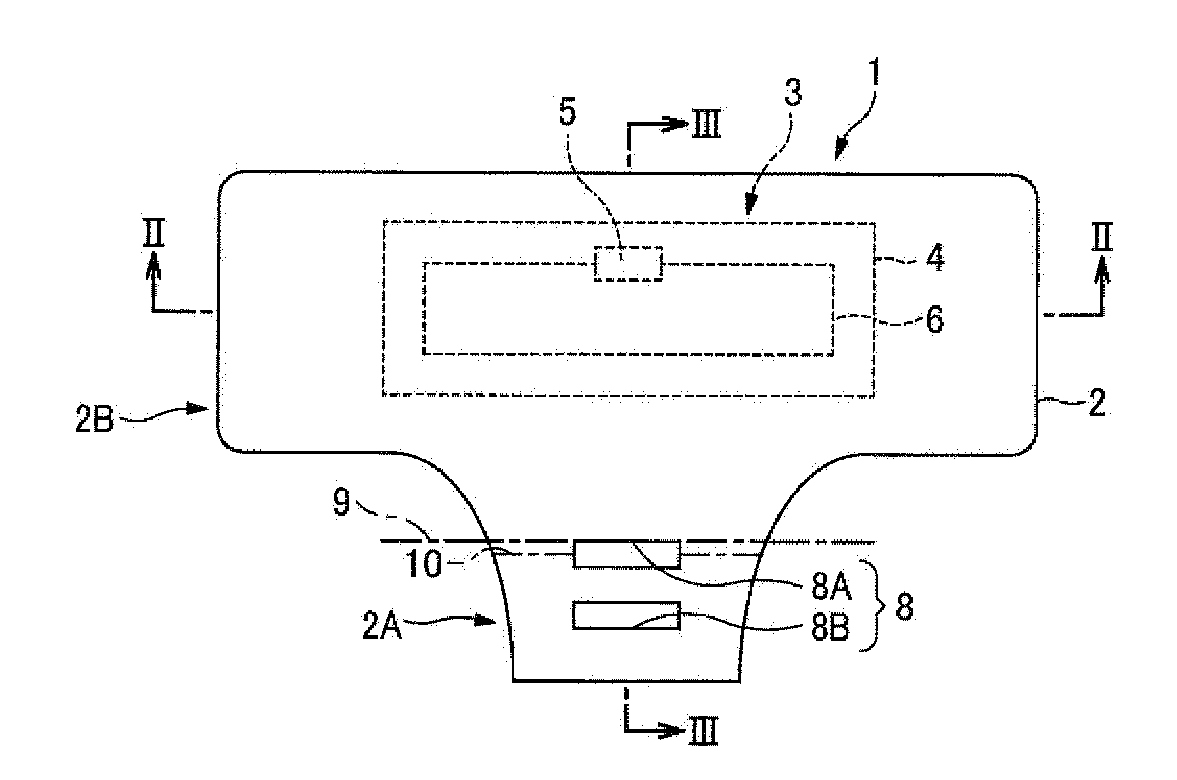
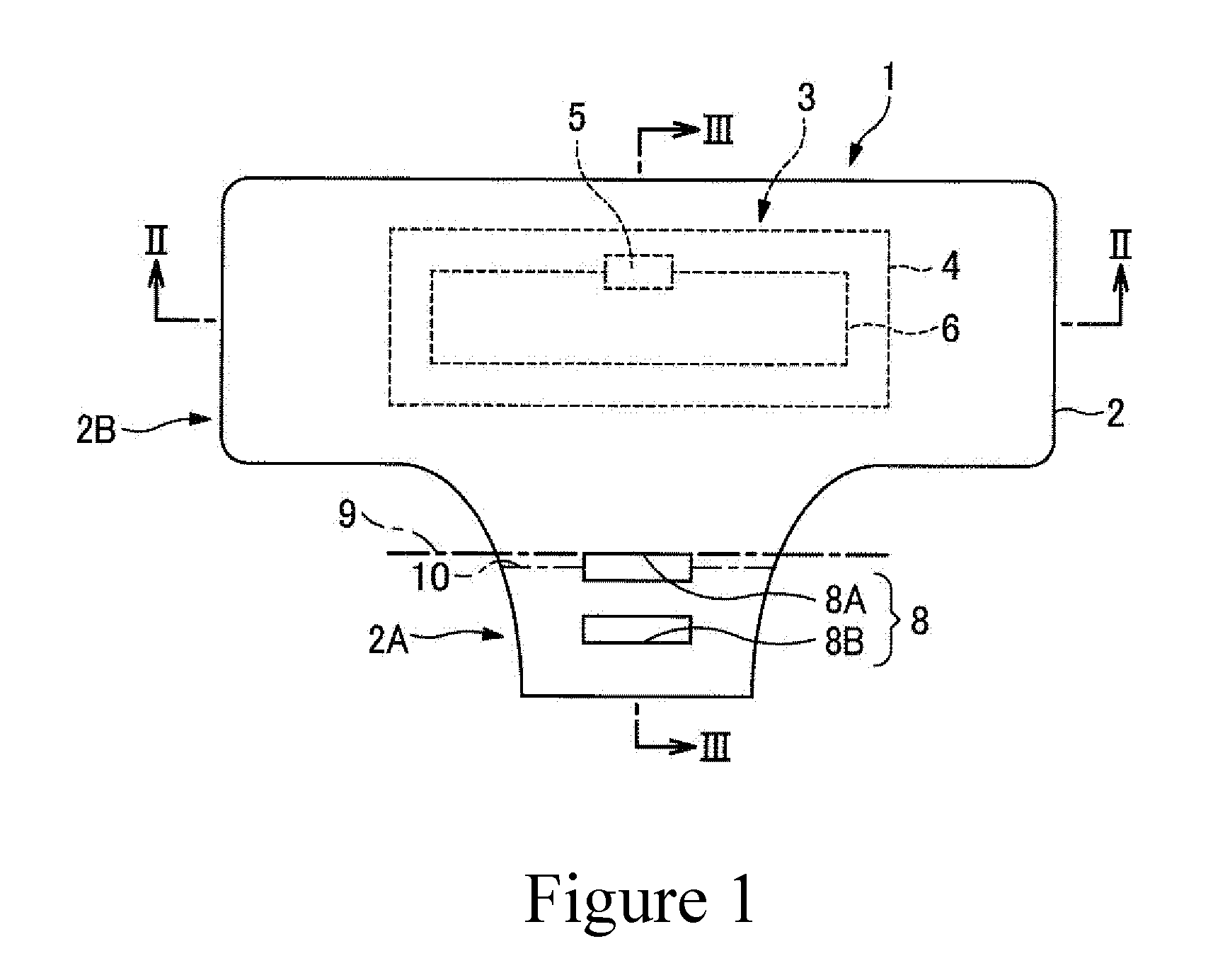
[0038]Hereinafter, an RFID tag 1 of a first embodiment according to the present invention, and a method of attaching the RFID tag 1 will be described.

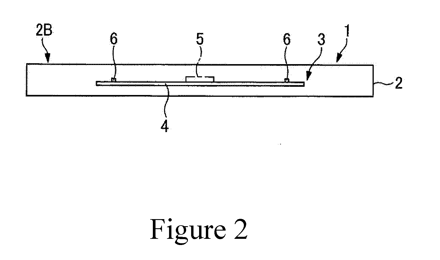
[0039]The RFID tag 1 includes a tag base 2 and an RFID inlet 3.

[0040]The tag base 2 comprises a base sheet comprised, for example, of a synthetic resin having predetermined flexibility or elasticity, and rigidity. The tag base 2 has the RFID inlet 3 contained therein.

[0041]The RFID inlet or support 3 includes an inlet base 4 comprised, for example, of polyethylene terephthalate or a film stack of polyethylene terephthalate, an IC chip 5 on the film or the stack thereof, and an RFID antenna 6, and this assembly is able to perform wireless data communication. The RFID inlet 3 performs reading and writing of data required for the IC chip 5 wirelessly via the RFID antenna 6 (data communication) based on an electromagnetic effect of radio waves in a predetermined frequency band such as a UHF band (300 MHz to 3 GHz (preferably, 860 MHz to 96...


PUM

PropertyMeasurementUnit
frequencyaaaaaaaaaa
frequencyaaaaaaaaaa
frequencyaaaaaaaaaa

Abstract

An RFID tag for stably holding an RFID inlet 3 raised and spaced apart with respect to an article, on which the tag is placed and a method of attaching such an RFID tag. Allow the RFID tag to be raised from a surface of an article by being flexed to bring the RFID tag into contact with a head portion of a banding band. A through hole 8 defined in a tag base 2 allows insertion of the banding band. The hole 8 includes a first through bore 8A and a second through bore 8B. The tag base 2 includes a base region 2A for raising a holding region and a holding region 2B for an RFID inlet 3 for being reused. The base region 2A raises an RFID inlet 3 with respect to an article, and the holding region inlet 2B having the RFID inlet 3 is allowed to be raised from the base region.

Description

CROSS-REFERENCE TO RELATED APPLICATIONS[0001]The present application is a 35 U.S.C. §§371 national phase conversion of PCT / JP2012 / 081514, filed Dec. 5, 2012, which claims priority of Japanese Patent Application No. 2012-004576, filed Jan. 13, 2012, the contents of which are incorporated by reference herein. The PCT International Application was published in the Japanese language.TECHNICAL FIELD[0002]The present invention relates to RFID (Radio Frequency Identification) tags and methods of attaching the RFID tags, and in particular to an RFID tag to be attached to a metallic material and a method of attaching the RFID tag.BACKGROUND ART[0003]Conventionally, an RFID tag provided with an RFID inlet having an IC chip and an RFID antenna and capable of wirelessly writing or reading data has been utilized for data management of required data in various fields by attaching the tag to an article of various types and reading and writing various data relating to the article.[0004]However, in ...

Claims


Application Information

Patent Timeline
Patent Type & Authority Applications(United States)
IPC IPC(8): G06K19/077G06K19/07
CPCG06K19/07758G06K19/07722G06K19/0723G06K19/077G06K19/07777G06K19/07762G06K19/07771Y10T29/49018
Inventor NITTA, HARUHIKO
Owner SATO HLDG CORP
Learn More