
Optical fiber terminal fixing tool for winding optical fiber and optical fiber winding method

a technology of optical fiber and fixing tool, which is applied in the direction of thin material handling, instruments, fibre mechanical structures, etc., to achieve the effects of improving labor-saving and efficiency, facilitating introduction, and narrow width

Active Publication Date: 2015-01-08
THE FUJIKURA CABLE WORKS LTD
View PDF1 Cites 9 Cited by
  • Summary
  • Abstract
  • Description
  • Claims
  • Application Information

AI Technical Summary

Benefits of technology

The present invention aims to improve labor-saving and efficiency in a winding operation using a bobbin with a narrow width without requiring manual operation. The technical effects of the invention include securing and easily introducing optical fiber to the winding portion with a narrow width using an optical fiber terminal fixing tool, automizing the winding operation of the optical fiber with respect to the narrow width without requiring manual operation, and achieving space saving and decreasing the time required to start the winding with respect to the narrow width.

Problems solved by technology

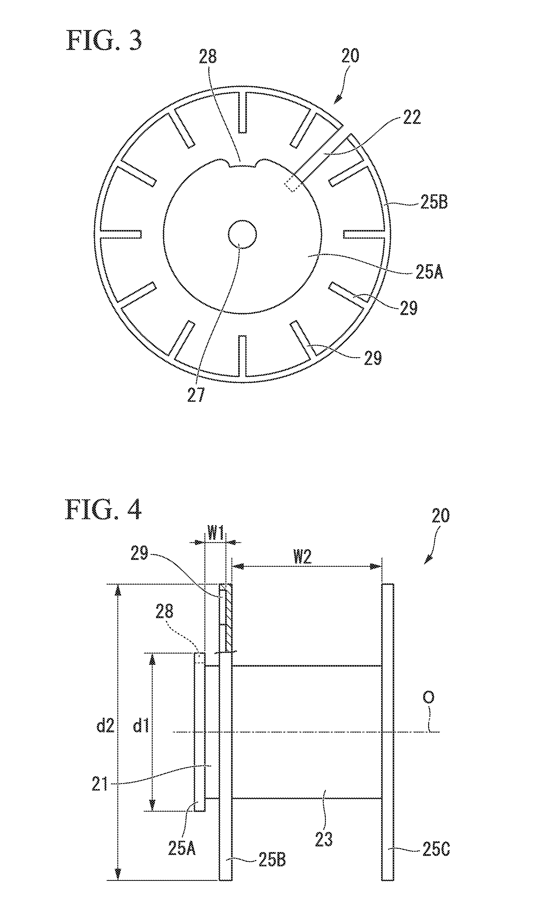
Accordingly, the winding of the optical fiber 11 on the narrow width winding portion 21 is a big problem with respect to labor-saving in the winding process in regard to the overall automation of the optical fiber winding, and productivity improvement.
However, even though the bobbin is a bobbin having only one winding portion, when the width of the winding portion is significantly narrow, the above-described problem occurs.

Method used


Image

  • Optical fiber terminal fixing tool for winding optical fiber and optical fiber winding method
  • Optical fiber terminal fixing tool for winding optical fiber and optical fiber winding method
  • Optical fiber terminal fixing tool for winding optical fiber and optical fiber winding method

Examples


Embodiment Construction

[0062]Hereinafter, an embodiment of the present invention will be described in detail.

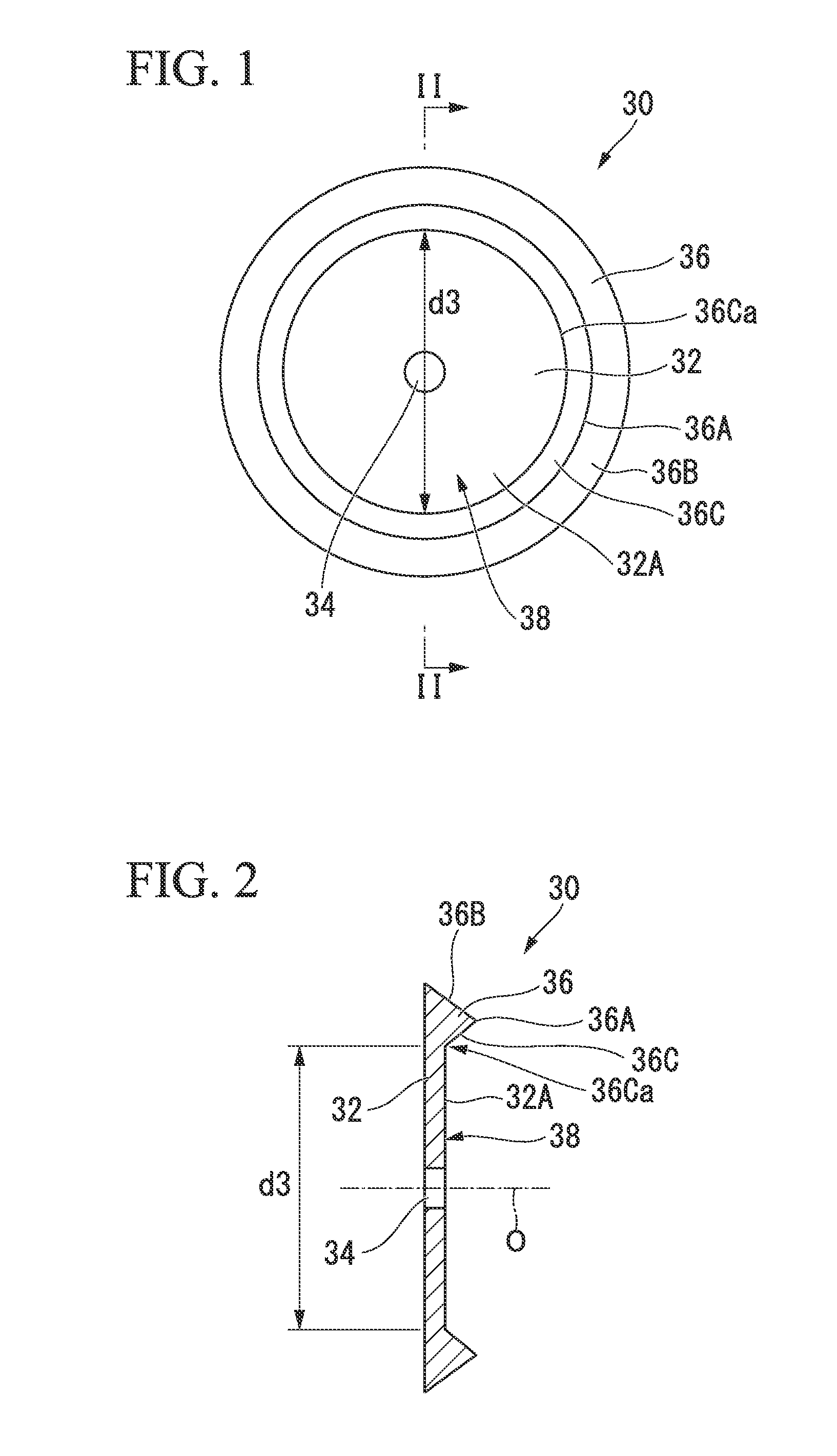
[0063]FIGS. 1 and 2 show the overall configuration of an optical fiber terminal fixing tool according to an embodiment of the present invention.

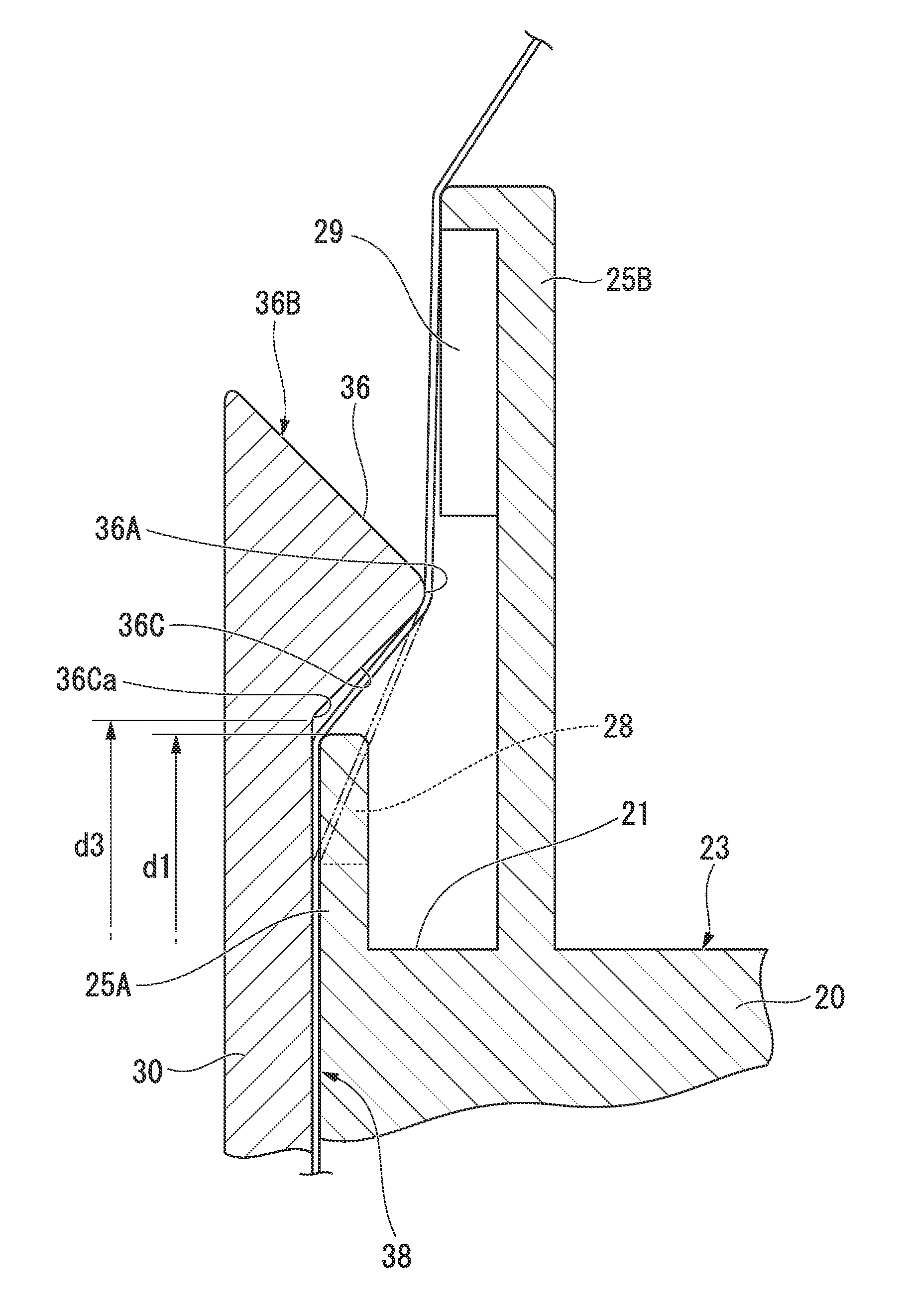
[0064]In FIGS. 1 and 2, for example, an optical fiber terminal fixing tool 30 is configured of a substrate (disc-shaped substrate) 32 formed in a disc shape as a whole by a relatively hard resin such as ABS resin or a metal such as aluminum. A shaft hole 34, through which a rotating shaft (not shown) of a winding machine is inserted, is formed on a center portion of the disc-shaped substrate 32 so as to penetrate along a central axis O. Moreover, an annular protrusion 36 protruding in a direction parallel to the central axis O is formed on a portion close to an outer circumferential edge on one plate surface 32A of the disc-shaped substrate 32.

[0065]The protrusion 36 continues along the circumferential direction of the disc-shaped substrate 32. A cross-sect...


PUM


Abstract

An optical fiber terminal fixing tool includes: a disc-shaped substrate having a plate surface; a holding surface which is provided on the plate surface and interposes the terminal portion of the optical fiber between the holding surface and the first flange portion; and a protrusion which continues in a circumferential direction with a larger diameter than an outer diameter of the first flange portion in an outer circumferential portion on the plate surface while protruding toward the bobbin in a state where the fixing tool is mounted on the rotating shaft of the optical fiber winding machine.

Description

BACKGROUND OF THE INVENTION[0001]1. Field of the Invention[0002]The present invention relates to an optical fiber terminal fixing tool for fixing a winding start end of an optical fiber to a bobbin and a method for winding the optical fiber on the bobbin using the fixing tool at the time of winding start when the optical fiber is wound around a winding portion between flange portions of the optical fiber winding bobbin having the flange portion. Particularly, the present invention relates to an optical fiber terminal fixing tool suitable for introducing an optical fiber having a terminal fixed to a bobbin to a winding portion, and a winding method using the fixing tool.[0003]Priority is claimed on Japanese Patent Application No. 2013-138935, filed on Jul. 2, 2013, the content of which is incorporated herein by reference.[0004]2. Description of Related Art[0005]In a manufacturing method for an optical fiber wire, a manufacturing method for an optical fiber core wire, or the like, the...

Claims


Application Information

Patent Timeline
Patent Type & Authority Applications(United States)
IPC IPC(8): G02B6/44B65H54/00B65H65/00
CPCG02B6/4457B65H54/00B65H65/00B65H2701/32
Inventor AKAMATSU, TSUYOSHI
Owner THE FUJIKURA CABLE WORKS LTD
Learn More