Video display device and television receiving device

a technology for video display and television, which is applied in the direction of television systems, instruments, and image enhancement, can solve the problems of degrading display quality and ineffective increase contrast, and achieve the effects of preventing degrading display quality, enhancing brightness, and improving contras

Inactive Publication Date: 2015-01-08
SHARP KK
View PDF7 Cites 31 Cited by
  • Summary
  • Abstract
  • Description
  • Claims
  • Application Information

AI Technical Summary

Benefits of technology

[0028]According to the present invention, in a video display device that divides a backlight into a plurality of areas to control luminance of the backlight according to a video signal corresponding to each area, it is possible that while power limit control is being performed, a bright video is made much brighter so as to improve contrast and enhance feeling of brightness for a high-luminance video and further, even when an OSD image is displayed, display quality is prevented from being degraded.

Problems solved by technology

Because of such limit, even when trying to improve contrast, for example, by making a bright video much brighter uniquely by local dimming, there are limitations and it is impossible to increase contrast effectively.
Meanwhile, in a display device that realizes improvement of image quality and reduction of power consumption by optimizing screen luminance dynamically according to an input video signal, when an OSD (On Screen Display) image is superimposed, luminance of a display area of the OSD image fluctuates to thereby degrade display quality.

Method used


Image

  • Video display device and television receiving device
  • Video display device and television receiving device
  • Video display device and television receiving device

Examples


Embodiment Construction

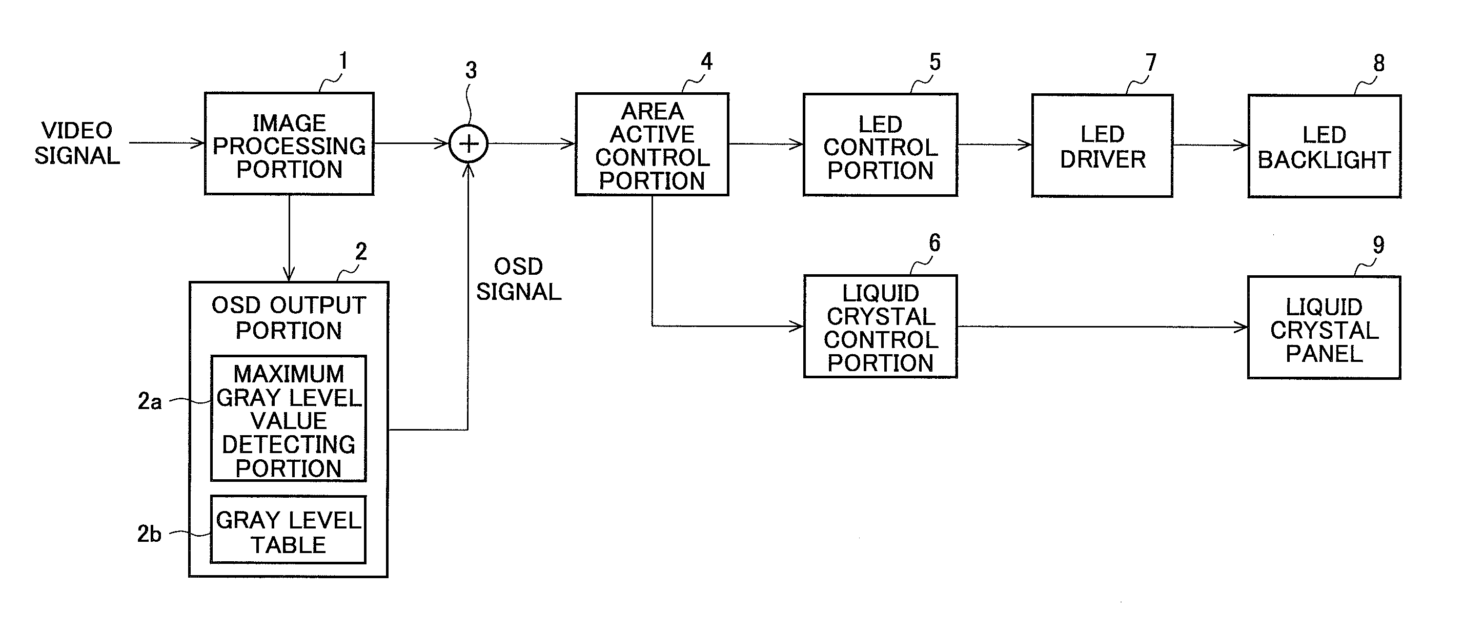
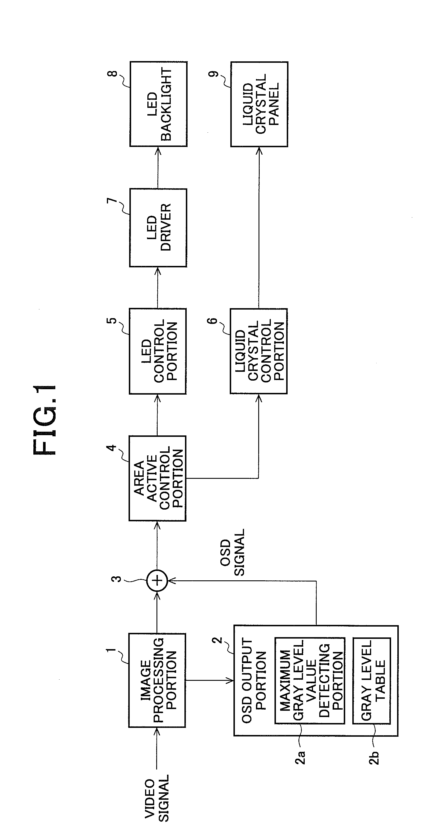
[0047]FIG. 1 is a diagram describing one embodiment of a video display a device according to the present invention and shows an exemplary configuration of a main part of the video display device. The video display device has a configuration that applies image processing to an input video signal for video display, and is able to be applied to a television receiving device or the like.

[0048]The video display device illustrated in FIG. 1 is provided with an image processing portion 1, an OSD output portion 2, a synthesizing portion 3, an area active control portion 4, an LED control portion 5, a liquid crystal control portion 6, an LED driver 7, an LED backlight 8, and a liquid crystal panel 9. Note that, a part of the area active control portion 4, the LED control portion 5 and the LED driver 7 for controlling light emission of the LED backlight 8 correspond to an example of the above-described backlight control portion of the present invention.

[0049]The image processing portion 1 inp...


PUM


Abstract

Provided is a video display device wherein a light emission luminance control is performed in accordance with a video signal corresponding to each of a plurality of divisional areas of a backlight. In the video display device: while power limiting control is being performed, the contrast can be improved and further the feeling of brightness for a high-luminance video can be increased; and even when an OSD image is displayed, display quality can be prevented from being degraded. A backlight control portion of the video display device defines a first luminance of LED for each divisional areas according to a first feature amount for a video indicated by a video signal after synthesizing of an OSD signal to be displayed in a display area corresponding to the divisional area, and controls the LED light emission by uniformly multiplying the first luminance by constant scale factor in a range where a total value of the LED drive current is equal to or less than a predetermined allowable current value. An OSD output portion (2) determines and outputs the OSD signal by use of gray scale data that is associated with a second feature amount of the video indicated by an input video signal to be displayed in a display area of the OSD image (or by an input video signal to be displayed in a display area corresponding to the divisional area including the display area of the OSD image).

Description

TECHNICAL FIELD[0001]The present invention relates to a video display device and a television receiving device, and more specifically relates to a video display device that divides a backlight into areas to control light emission luminance for each area and a television receiving device.BACKGROUND OF THE INVENTION[0002]In a video display device, one using an LED backlight for illumination of a display panel is prevalent. In the case of the LED backlight, there is an advantage that local dimming is possible. In the local dimming, a backlight is divided into a plurality of areas to control light emission of an LED for each area according to a video signal of a display area corresponding to each area. For example, such control becomes possible that light emission of the LED is suppressed for a dark part in a screen and the LED is caused to emit light with high intensity for a bright part in the screen. This makes it possible to reduce power consumption of the backlight as well as to im...

Claims


Application Information

Patent Timeline
Patent Type & Authority Applications(United States)
IPC IPC(8): G09G3/34H04N5/74G09G3/36
CPCG09G3/3406G09G3/36G09G2320/062G09G2320/066H04N5/7408H04N5/202H04N5/57H04N5/66G02F2203/30H04N21/4436G06T5/008G09G3/3426G09G2320/0646G09G2330/021G09G2340/125G09G2360/16G02F1/133603G02F1/133601
Inventor KUDO, YOHEIIWASAKI, KOHJI
Owner SHARP KK
Why Eureka
Try Eureka