Illumination device and display device equipped with same
Active Publication Date: 2015-01-08
ENPLAS CORP
View PDF3 Cites 13 Cited by
Summary
Abstract
Description
Claims
Application Information
AI Technical Summary
This helps you quickly interpret patents by identifying the three key elements:
Problems solved by technology
Method used
Benefits of technology
Benefits of technology
The present invention provides an illumination device that can prevent the reflecting sheet around the light emitting element from rising while ensuring a stable fixing of the diffusing lens. This device may be used in a display device.
Problems solved by technology
In this case, there is a disadvantage that part of the light emitted from the LED 1011 goes under the reflecting sheet 1014; whereby brightness unevenness easily occurs and light loss occurs.
Method used
Image
Click on the blue label to locate the original text in one second.
Reading with bidirectional positioning of images and text.
Examples
first embodiment
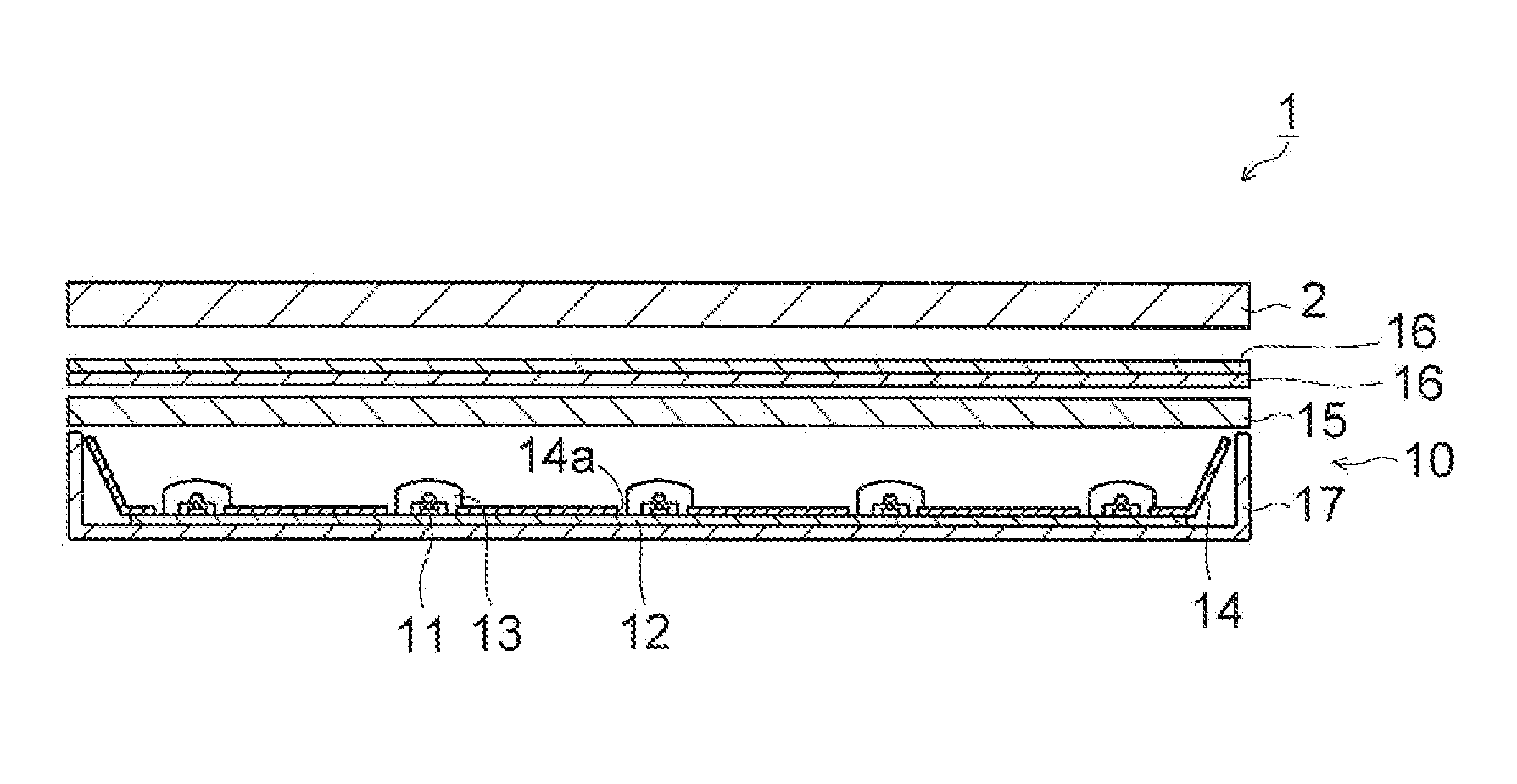
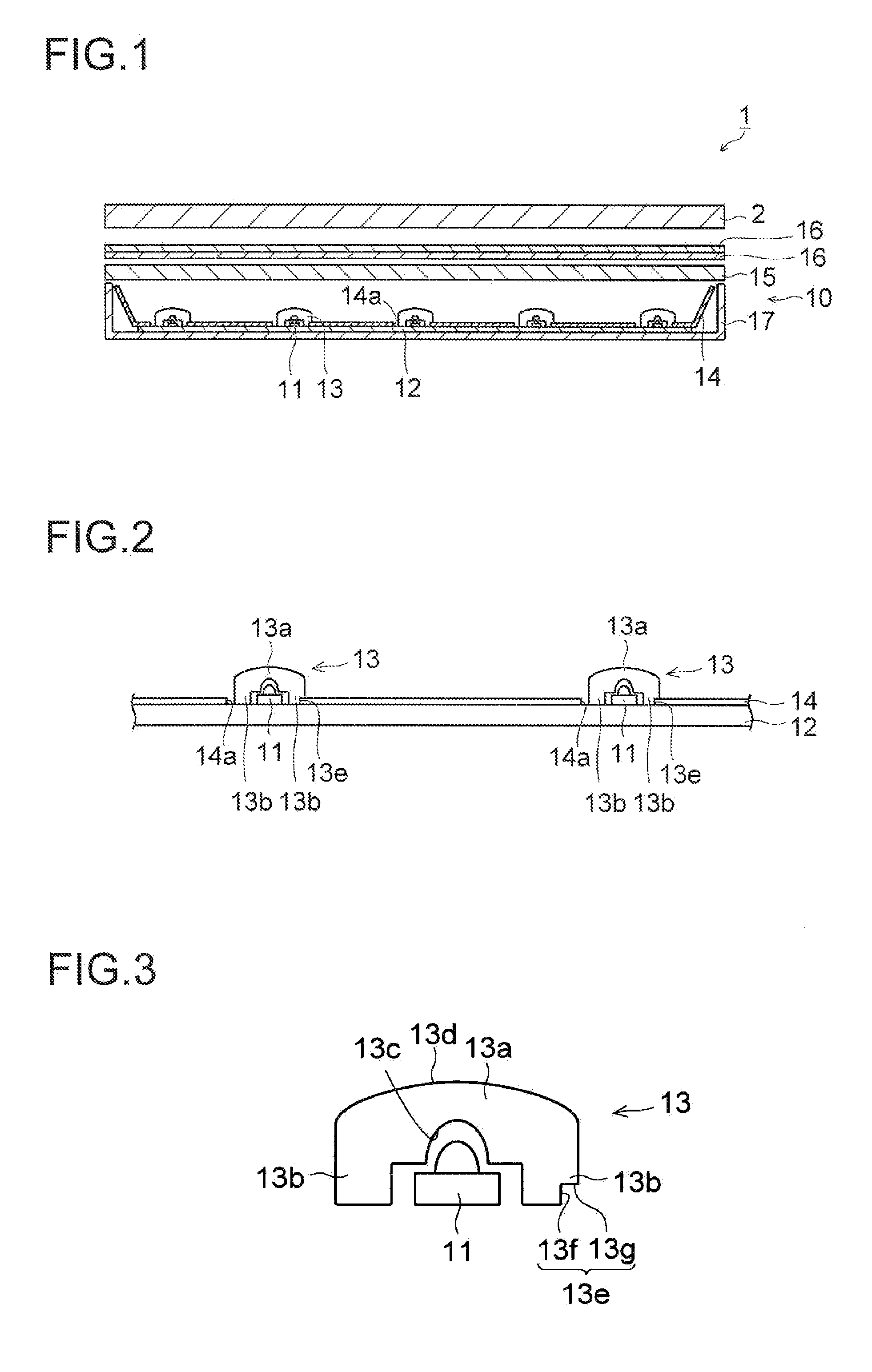
[0038]With reference to FIG. 1 to FIG. 5, a structure of a display device 1, which comprises an illumination device 10 according to an first embodiment of the present invention, is described. The display device 1 according to the first embodiment of the present invention is used for a television receiver and the like, for example, Besides, as shown in FIG. 1, the display device 1 comprises a display panel 2, and the illumination device 10 that is disposed near a rear side of the display panel 2 and illuminates the display panel 2.
[0039]The display panel 2 includes a liquid crystal display panel, and has two glass boards that sandwich a liquid crystal layer which is not shown. Besides, the display panel 2 uses light from the illumination device 10 to display an image.
[0040]The illumination device 10 is a backlight device of direct type. Besides, the illumination device 10 includes; a plurality of light emitting elements 11; a mounting board 12 on which the plurality of light emitting...
second embodiment
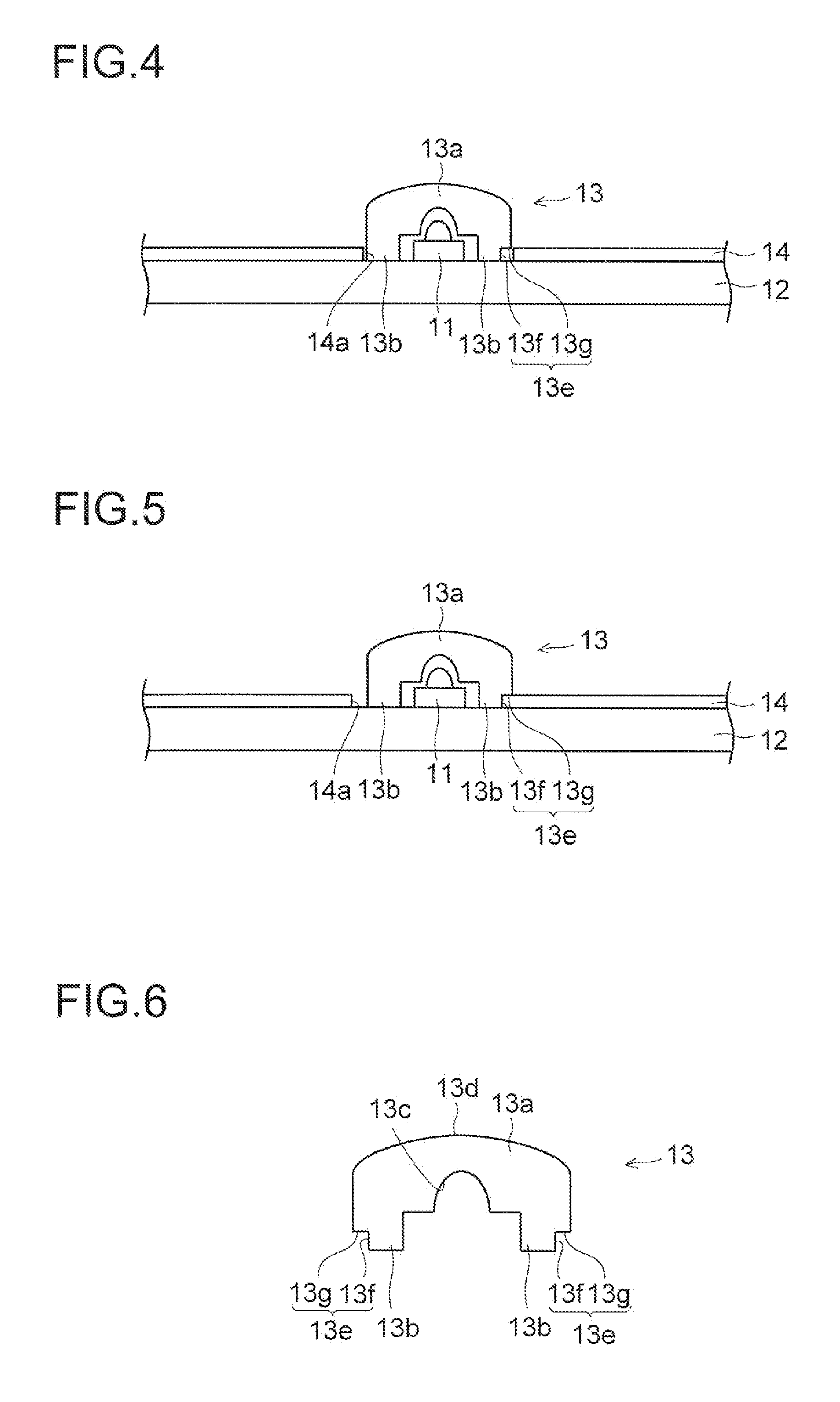
[0056]As shown in FIG. 6, in a second embodiment of the present invention, the diffusing lens 13 includes a plurality of (e.g., three) fixing portions 13b, and the engaging portion 13e is formed on the outer portions (opposite portion with respect to the center of the lens portion 13a) of all the fixing portions 13b.
[0057]The other structures of the second embodiment are the same as the above first embodiment.
[0058]In the present embodiment, as described above, the engaging portion 13e is formed on all the fixing portions 13b. In this way, when fixing the diffusing lenses 13 to the mounting, board 12, it becomes unnecessary to align the directions (mounting directions) of the diffusing lenses 13; accordingly, it is possible to improve the mounting work of the diffusing lenses 13.
[0059]The other effects of the second embodiment are the same as the above first embodiment.
[0060]In the meantime, it should he considered that the embodiments disclosed this time are examples in all respec...
PUM
Abstract
Provided is an illumination device capable of preventing a reflection sheet in the periphery of a light-emitting element from being raised while minimizing the instability in the fixture of a diffusion lens. The illumination device comprises a light-emitting element, a mounting substrate, a diffusion lens, and a reflection sheet having a through-hole. The diffusing lens includes a lens portion for diffusing light, and a fixed portion to be fixed to the mounting substrate. An engaging portion that sandwiches the reflection sheet between the engaging portion and the mounting substrate is formed in the fixed portion.
Description
TECHNICAL FIELD[0001]The present invention relates to an illumination device and a display device that comprises the same, more particularly, to an illumination device that includes a reflecting sheet and to a display device that comprises the same.BACKGROUND ART[0002]In a liquid crystaldisplay device (display device), a display panel is of non light emitting type; accordingly, usually, a backlight device (illumination device), which shines light onto the display panel, is incorporated. As such a backlight device, a backlight device of direct type is known, which comprises a plurality of LEDs (light emitting element) and a reflecting sheet that reflects light emitted from the LED to a display panel.[0003]FIG. 7 is a cross-sectional view showing schematically a structural example of a conventional display device that comprises a backlight device of direct type that includes a plurality of LEDs and a reflecting sheet. FIG. 8 and FIG. 9 are each a cross-sectional view showing a struct...
Claims
Application Information
Patent Timeline
Application Date:The date an application was filed.
Publication Date:The date a patent or application was officially published.
First Publication Date:The earliest publication date of a patent with the same application number.
Issue Date:Publication date of the patent grant document.
PCT Entry Date:The Entry date of PCT National Phase.
Estimated Expiry Date:The statutory expiry date of a patent right according to the Patent Law, and it is the longest term of protection that the patent right can achieve without the termination of the patent right due to other reasons(Term extension factor has been taken into account ).
Invalid Date:Actual expiry date is based on effective date or publication date of legal transaction data of invalid patent.

