Cooling system, reservoir unit and cartridge, as well as solid-state laser oscillator system provided with the same

a laser oscillator and reservoir technology, which is applied in the direction of domestic cooling apparatus, semiconductor/solid-state device details, active medium materials, etc., can solve the problems of troublesome replacement work, electric leakage, and possible spillage of coolant, so as to facilitate the replacement work of the circulating

Active Publication Date: 2015-01-08
FUJIFILM CORP
View PDF4 Cites 14 Cited by
  • Summary
  • Abstract
  • Description
  • Claims
  • Application Information

AI Technical Summary

Benefits of technology

[0028]According to the cooling system, the reservoir unit and the cartridge according to the invention, as well as the solid-state laser oscillator system provided with them, the cartridge-type tank is used to store the circulating liquid, such as a coolant, and collection and replacement of the circulating liquid fed to the circulation path can be achieved only by removing and attaching the cartridge from and to the cartridge loading unit. This facilitates the replacement work of the circulating liquid with the cooling system in which the circulating liquid is circulated.

Problems solved by technology

The above-described replacement work, however, has problems, such that the replacement work needs to be conducted by a person with expertise about the cooling system, the replacement work is troublesome, the coolant maybe spilled, etc.
For example, spilled coolant on a high voltage portion of the laser may cause electric leakage, and the spilled coolant itself is not desirable in view of sanitation in a medical setting, etc.

Method used


Image

  • Cooling system, reservoir unit and cartridge, as well as solid-state laser oscillator system provided with the same
  • Cooling system, reservoir unit and cartridge, as well as solid-state laser oscillator system provided with the same
  • Cooling system, reservoir unit and cartridge, as well as solid-state laser oscillator system provided with the same

Examples


first embodiment

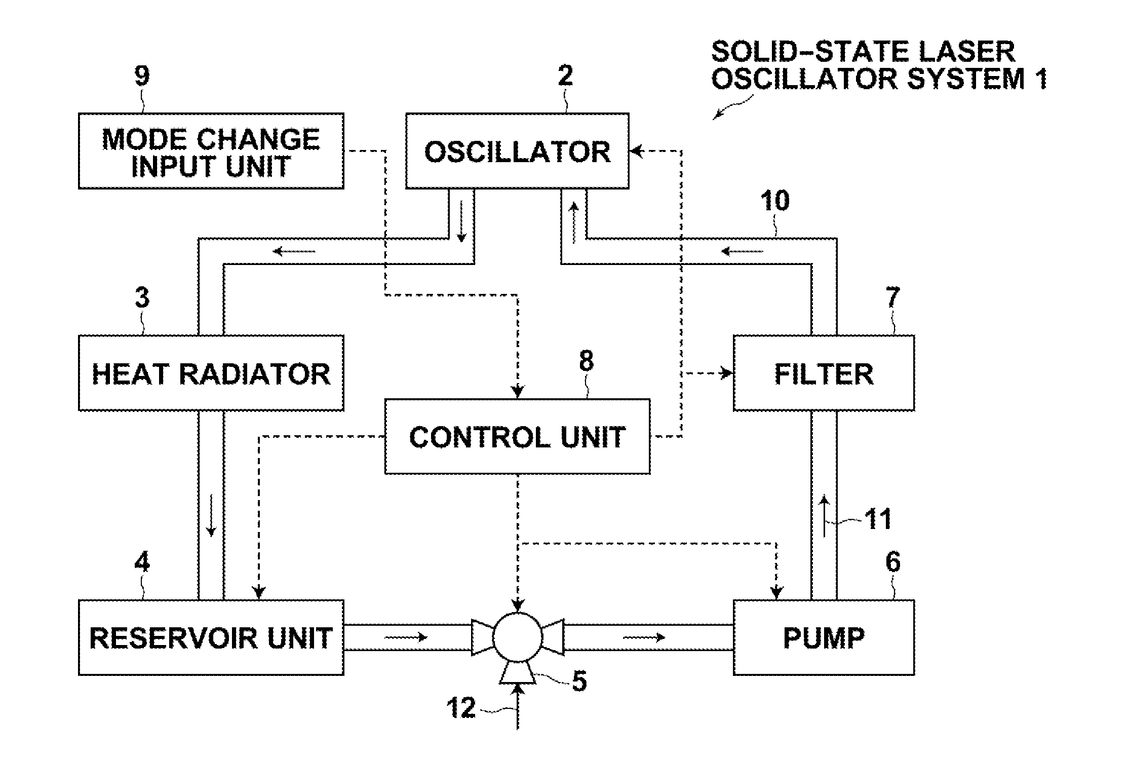
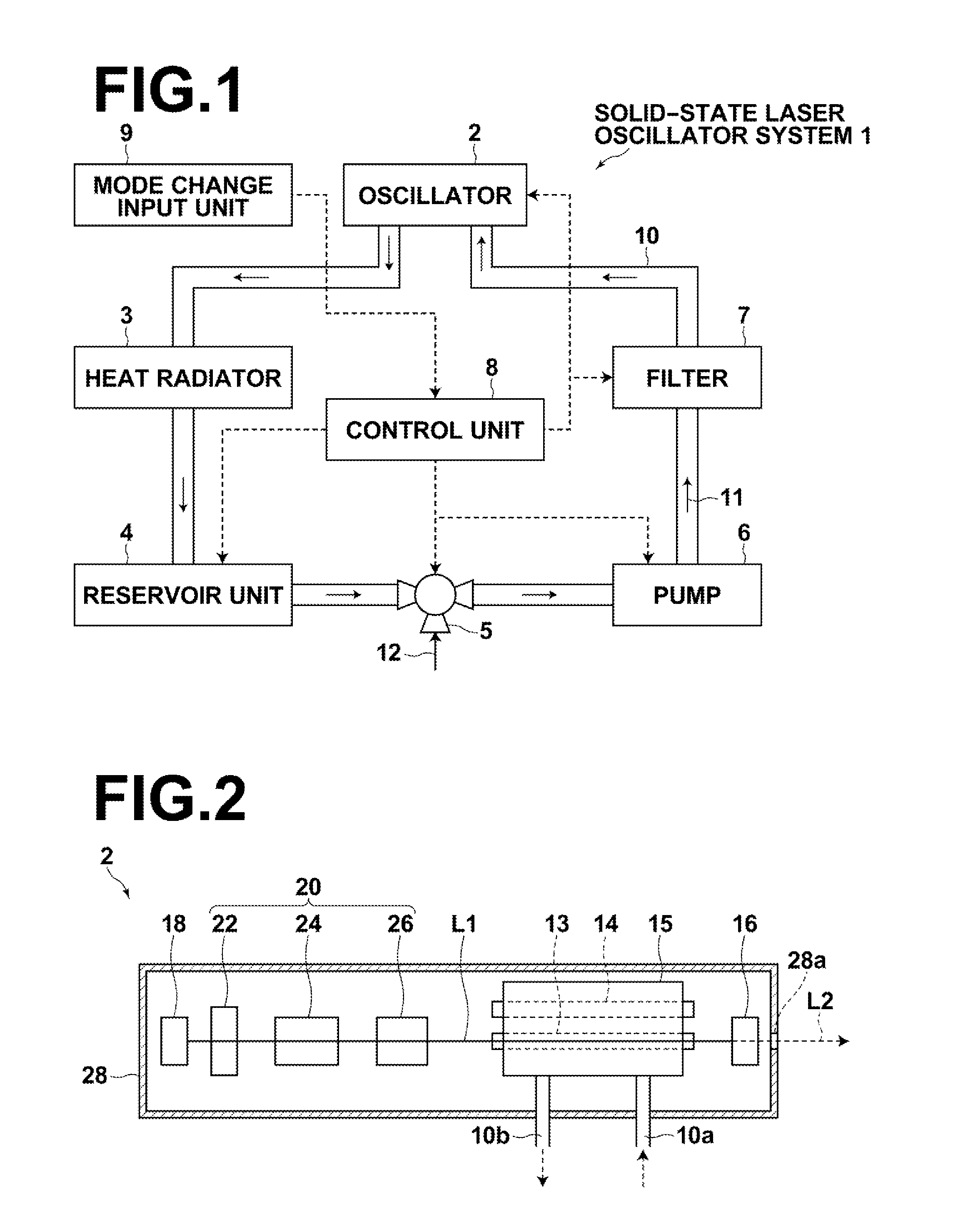
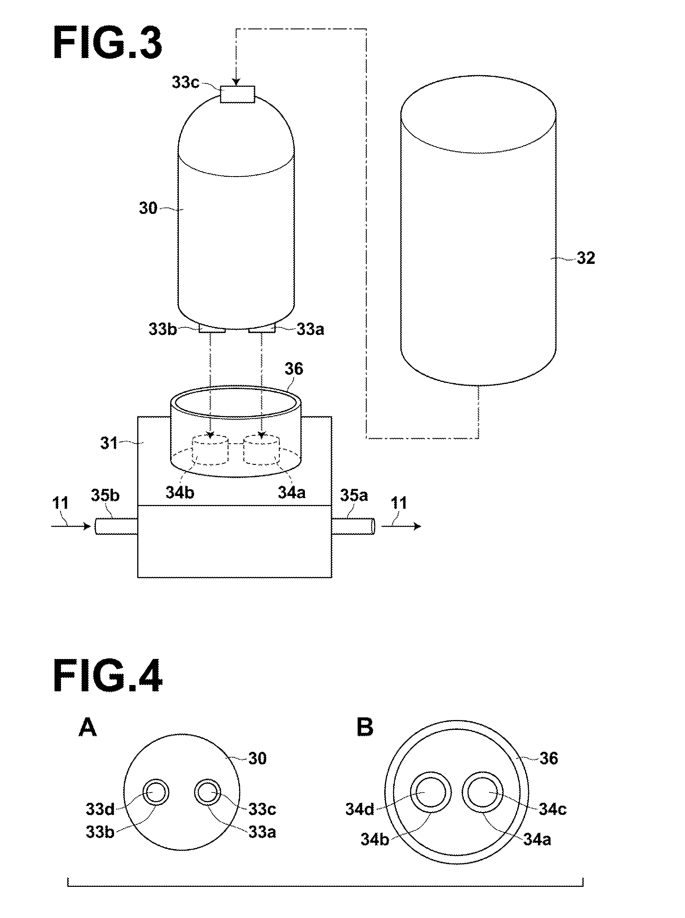
[0045]Now, a first embodiment of a cooling system and a reservoir unit, as well as a solid-state laser oscillator system including them is described. FIG. 1 is a schematic block diagram illustrating the configuration of a cooling system of this embodiment, and FIG. 2 is a schematic sectional view illustrating the configuration of an oscillator 2 of a solid-state laser oscillator system 1. Further, FIG. 3 is a schematic perspective view illustrating the structure of a reservoir unit 4 of this embodiment.

[0046]As shown in FIG. 1, the solid-state laser oscillator system 1 of this embodiment includes: an oscillator 2 that emits laser light;

[0047]a circulation path 10 including the oscillator 2 serving as a heat absorbing section of the invention, and including a heat radiator (radiator) 3 forming a heat release section of the invention, a reservoir unit 4, a valve 5, a pump 6 and a filter 7 in this order as elements along the path; a control unit 8 that controls the entire system; and a...

second embodiment

[0076]Next, a second embodiment of the cooling system, the reservoir unit and the cartridge, as well as the solid-state laser oscillator system provided with them is described. The difference between this embodiment and the first embodiment lies in the structures of the cartridge and the cartridge loading unit. Therefore the same features as those of the first embodiment are not described in detail unless otherwise necessary. It should be noted that the similar elements are denoted by the same reference numerals as long as there is no inconvenience.

[0077]FIG. 9 is a schematic view showing, at A, the structure of a cartridge 45 of this embodiment viewed from below, and showing, at B, the structure of a cartridge loading unit of this embodiment viewed from above. FIG. 10 is a schematic view showing a cross-section taken along the line A-A of reservoir chambers of the cartridge 45 of this embodiment.

[0078]Similarly to the first embodiment, the solid-state laser oscillator system 1 of t...

third embodiment

[0088]Next, a third embodiment of the cooling system, the reservoir unit and the cartridge, as well as the solid-state laser oscillator system provided with them is described. The difference between this embodiment and the first embodiment lies in that the cooling system of this embodiment includes a first monitoring unit for monitoring the optical pumping intensity of the pumping lamp 14, and a second monitoring unit for monitoring the output intensity of the laser light L2 outputted from the oscillator 2. Therefore the same features as those of the first embodiment are not described in detail unless otherwise necessary. It should be noted that the similar elements are denoted by the same reference numerals as long as there is no inconvenience.

[0089]FIG. 12 is a schematic view showing an area around the laser chamber 15 of this embodiment and the configuration of the second monitoring unit.

[0090]As shown in FIG. 12, the solid-state laser oscillator system 1 of this embodiment inclu...


PUM


Abstract

A reservoir unit which is included as an element along a circulation path of a cooling system includes a cartridge and a cartridge loading unit which are configured to be removable from each other. The cartridge includes a reservoir chamber that stores a circulating liquid, and a connection portion in fluid communication with the reservoir chamber. The cartridge loading unit includes a connection receiving portion, to which the connection portion is connected, and a connection port. When the cartridge and the cartridge loading unit are attached to each other, the connection portion, the connection receiving portion and the connection port form a feed path that allows feeding the circulating liquid to the circulation path outside, and a collection path that allows collecting the circulating liquid into the reservoir chamber.

Description

CROSS-REFERENCE TO RELATED APPLICATIONS[0001]This application is a Continuation of PCT International Application No. PCT / JP2013 / 002009 filed on Mar. 25, 2013, which claims priority under 35 U.S.C. §119(a) to Japanese Patent Application No. 2012-070512 filed on Mar. 27, 2012 and Japanese Patent Application No. 2013-035305 filed on Feb. 26, 2013. Each of the above applications is hereby expressly incorporated by reference, in its entirety, into the present application.BACKGROUND OF THE INVENTION[0002]1. Technical Field[0003]The present invention relates to a cooling system including a circulation path in which a coolant for cooling a heat source in a system circulates, and a reservoir unit and a cartridge used in the cooling system. The present invention also relates to a solid-state laser oscillator system provided with the cooling system.[0004]2. Background Art[0005]In the case of solid-state lasers, visible light or near-visible light is emitted from a flashlamp serving as an optic...

Claims


Application Information

Patent Timeline
Patent Type & Authority Applications(United States)
IPC IPC(8): H01S5/024F28F27/00F28F27/02
CPCH01S5/02423F28F27/00F28F27/02F25D17/02H01L23/473H01S3/042H01S3/092H01S3/115H01S3/025H01S3/0407H01S3/061H05K7/20254H01L2924/0002H01L2924/00H01S3/04H01S3/16
Inventor HIROTA, KAZUHIRO
Owner FUJIFILM CORP
Why Eureka
Try Eureka