
Hydraulic pressure bite-down dental impression

a dental impression and hydrostatic pressure technology, applied in the field of dental impression devices, systems and methods, can solve the problems of increasing the required time, materials, patient time, doctor time, etc., and achieving the effect of improving the quality of dental impressions

Active Publication Date: 2015-01-08
EVOLVE DENTAL TECH
View PDF1 Cites 26 Cited by
  • Summary
  • Abstract
  • Description
  • Claims
  • Application Information

AI Technical Summary

Benefits of technology

The patent describes a method and system for creating dental impressions using a two-step process. The first step involves using a first impression material to create a cavity in the dental object, while the second step involves using a second impression material to create a cavity with the same dimensions as the first step. The first impression material is forced into the dental object, while the second impression material fills the first impression. The method and system provide for improved accuracy and efficiency in creating dental impressions.

Problems solved by technology

Currently used dental impression techniques create predominantly unidirectional vertical pressure and consequently do not consistently capture sufficiently detailed reproductions of certain oral structures.
Another problem with these dental impression techniques is that they can allow the formation of bubbles and voids, typically called pulls, on and in the impressions.
The presence of such bubbles and pulls in impressions, particularly in critical areas of the oral impressions, renders the impression useless and necessitates that the impression be taken again, thereby increasing, among other things, the required time, materials, patient time, doctor time, and overall cost.
Commonly used techniques are particularly ill-adapted to capture slight or highly detailed structures, including but not limited to the small but very sharp crevice at the junction of the teeth and gums, generally known as the gingival crevice.

Method used


Image

  • Hydraulic pressure bite-down dental impression
  • Hydraulic pressure bite-down dental impression
  • Hydraulic pressure bite-down dental impression

Examples


Embodiment Construction

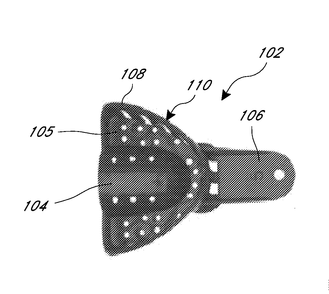
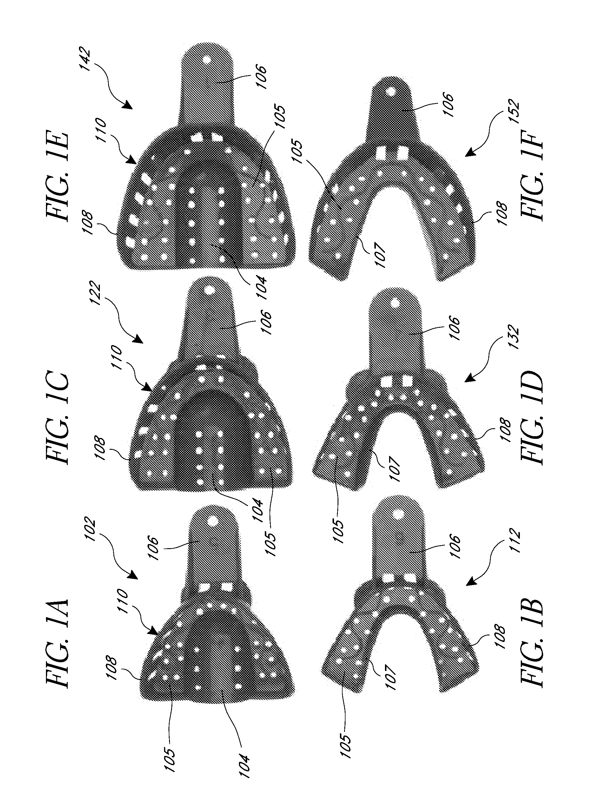
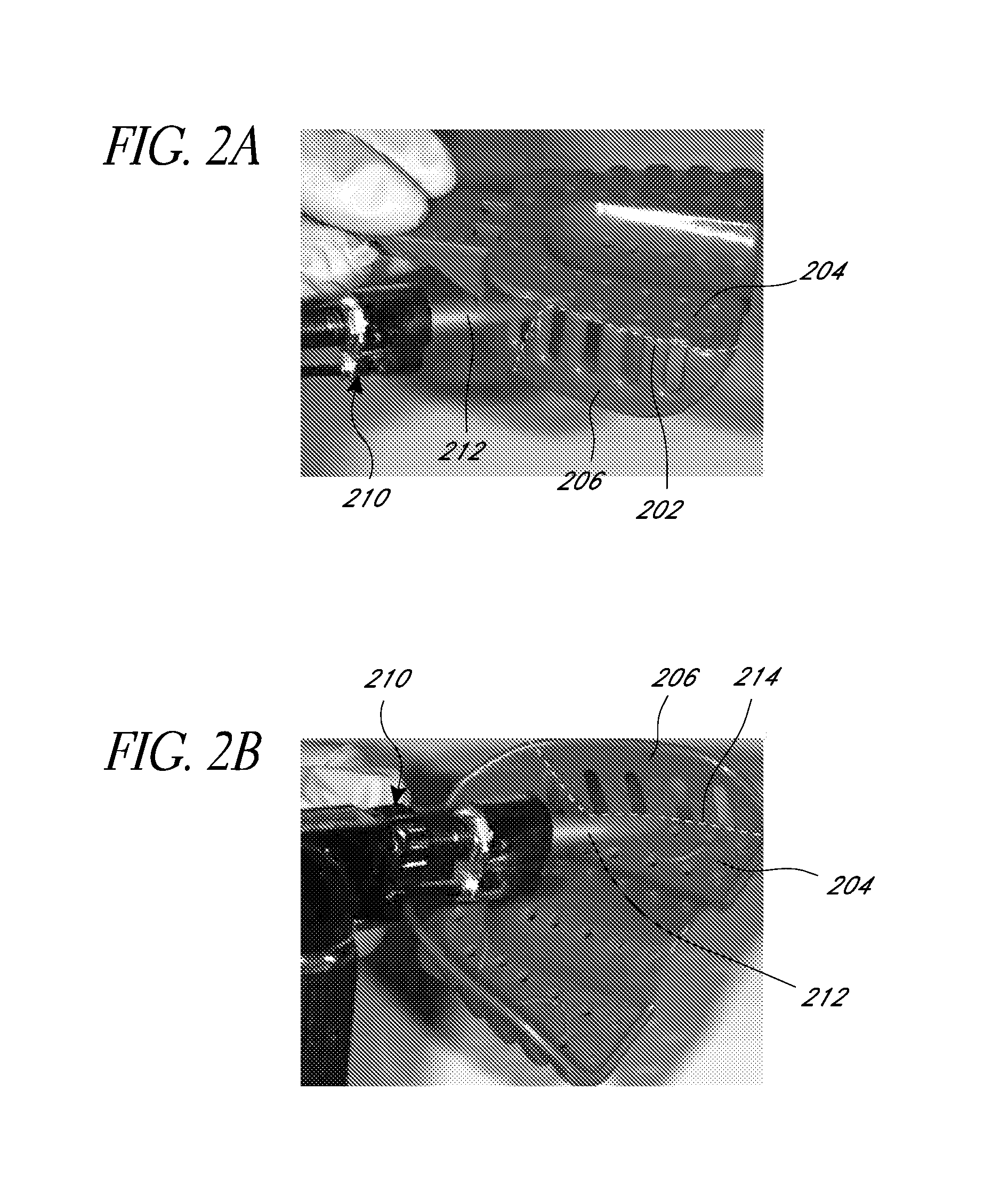
[0055]The hydraulic pressure dental impression technique is a two-step impression using a first impression (e.g., a base impression), taken as a first separate step, then a second impression (e.g., a wash impression), taken as a second separate step. Hydraulic pressure dental impressions may be used any time a dental impression is necessary where hard structures, such as teeth and / or dental implants, are present in the mouth. In some embodiments, hydraulic pressure dental impressions can be used for any of the following, but is not limited to the following: crowns, bridges, indirect restorations (e.g., inlays and onlays, etc.), tooth veneers (e.g., porcelain veneers and composite veneers, etc.), dental models, study models, orthodontic impressions for any type of orthodontic case (e.g., conventional orthodontics, short term orthodontics, clear aligner orthodontics, etc.), teeth whitening trays, athletic mouth guards, appliances used to reduce or protect from teeth grinding (e.g., br...


PUM


Abstract

In an exemplary embodiment, a method of creating an impression of structures of the human oral cavity comprises: preparing impression trays: creating a first, or base, impression; grinding out portions of the base impression; and using the void(s) in the ground out base impression to take a second, or wash, impression. The base impression is taken with an excess of a high-density impression material which is positioned to extend beyond the structures of interest (of which the impression is being taken). The base impression is removed and all fine structure surrounding the structure(s) of interest is ground out. A wash impression is then taken using a low-density impression material. The base impression creates a seal around the structure(s) of interest (a closed system), thereby producing omnidirectional hydraulic pressure on the low-density material. Such omnidirectional hydraulic pressure produces a highly detailed final impression from which a high-quality model (e.g., cast) can be made.

Description

INCORPORATION BY REFERENCE TO ANY PRIORITY APPLICATIONS[0001]Any and all applications for which a foreign or domestic priority claim is identified in the Application Data Sheet as filed with the present application are hereby incorporated by reference under 37 CFR 1.57.BACKGROUND OF THE INVENTION[0002]1. Field of the Invention[0003]The present invention relates to devices, systems and methods for dental impressions. More specifically, the present invention relates to devices, systems and methods for creating hydraulic pressure formed dental impressions.[0004]2. Description of the Related Art[0005]Requirements for the fabrication of many types of dental products (e.g., dental trays, orthodontic appliances, crowns, bridges, implants, study models, etc.) can be highly exacting. Therefore, these dental products require highly sophisticated and detailed molding procedures capable of capturing the required detail of the relevant oral structures. Currently used dental impression techniques...

Claims


Application Information

Patent Timeline
IPC IPC(8): A61C9/00
CPCA61C9/0006A61C3/02
Inventor KURTHY, RODGER
Owner EVOLVE DENTAL TECH
Learn More