Noncontact Power Supply System and Electromagnetic Induction Coil for Noncontact Power Supply Apparatus

Inactive Publication Date: 2015-01-15
HOSIDEN CORP
View PDF5 Cites 2 Cited by
  • Summary
  • Abstract
  • Description
  • Claims
  • Application Information

AI Technical Summary

Benefits of technology

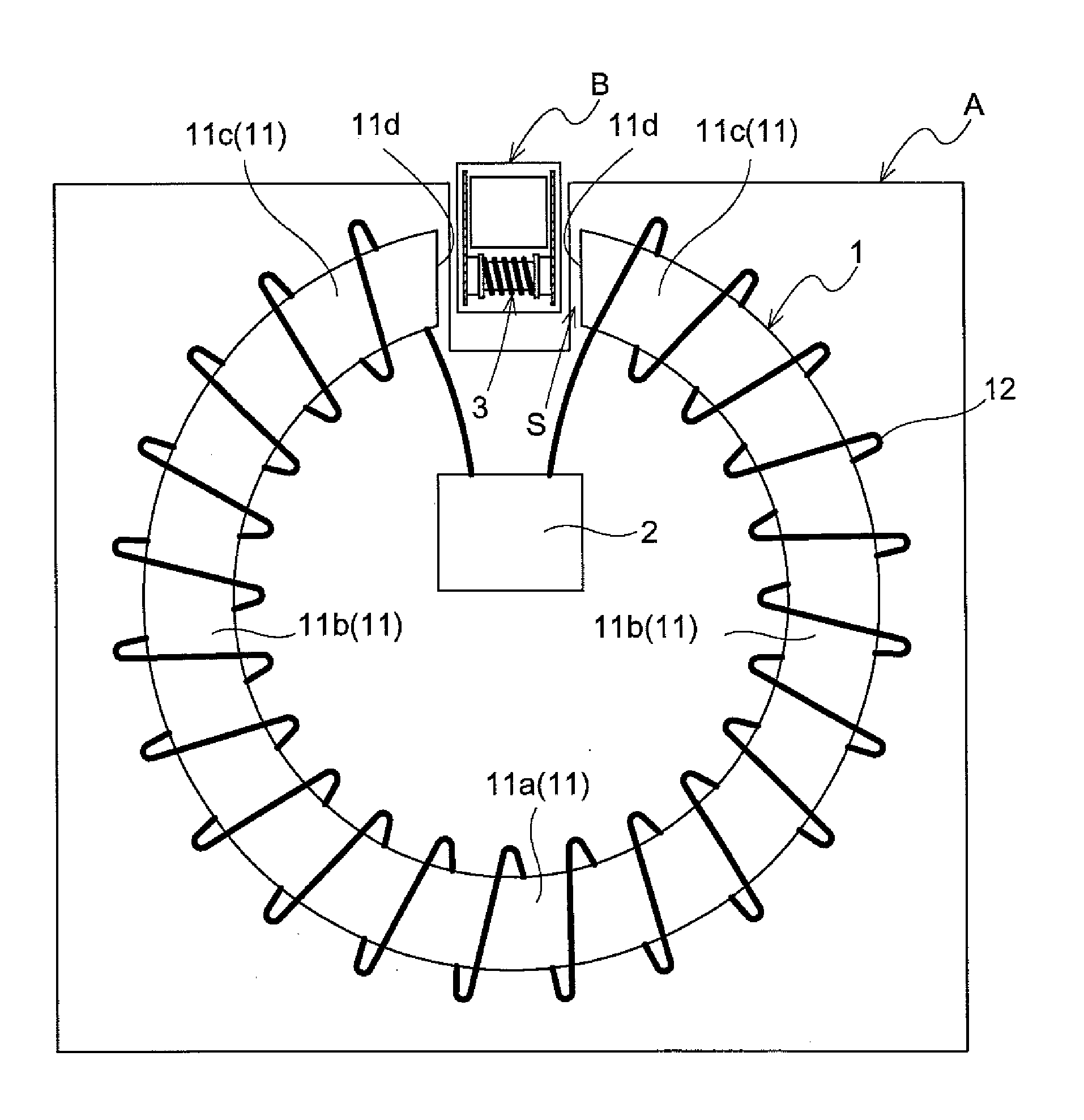
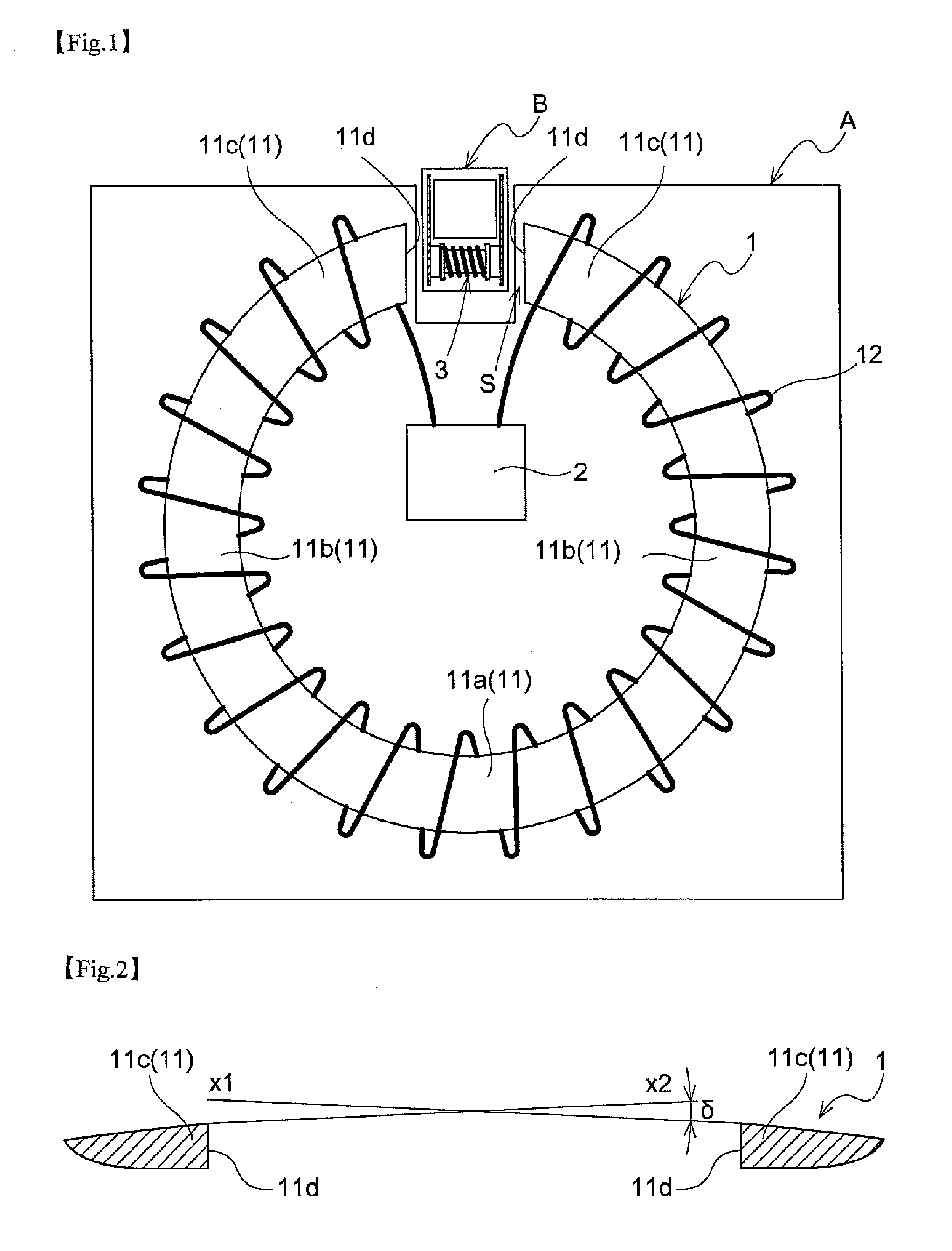
The present invention relates to an electromagnetic induction coil for noncontact power supply. The patent proposed a new design to improve power supply efficiency. The design includes a winding wire that is wound around only a small portion of the primary coil, which may lower the power supply efficiency. However, the winding wire has a higher density in the opposite segments than in the base segment. This arrangement enhances the power supply efficiency by increasing the density of magnetic fluxes that more contribute to power supply.

Problems solved by technology

On the other hand, with the plane coil disclosed in JP 2012-199505, there is a disadvantage that power supply efficiency is lowered due to positional displacement of the coil.
According to the arrangements disclosed in JP 9-238428 and JP 2005-137173, a winding wire is wound around only a small portion of the primary coil, which may lower the power supply efficiency.
In such a case, however, the electromagnetic induction coil disadvantageously generates heat.

Method used


Image

  • Noncontact Power Supply System and Electromagnetic Induction Coil for Noncontact Power Supply Apparatus
  • Noncontact Power Supply System and Electromagnetic Induction Coil for Noncontact Power Supply Apparatus
  • Noncontact Power Supply System and Electromagnetic Induction Coil for Noncontact Power Supply Apparatus

Examples


first embodiment

[0050]FIG. 6 is a schematic view of a primary coil 1 and a secondary coil 30. The primary coil 1 is built in an electric power supply apparatus (not shown) such as a charging device that supplies electric power to an electrical apparatus. On the other hand, the secondary coil 30 is built in the electrical apparatus (not shown) that receives electric power supply. While the primary coil 1 is connected to a power source and a power supply circuit, both of which are not illustrated in the drawing, the secondary coil 30 is connected to an unillustrated power receiving circuit. Electric power from the power receiving circuit is supplied to an electrical load such as the charging device of the electrical apparatus.

[0051]During power supply, the electric power supply apparatus and the electrical apparatus are positioned so that the primary coil 1 and the secondary coil 30 are arranged in a positional relationship shown in FIG. 6.

[0052]The secondary coil 30 is formed as an air-core coil hav...

second embodiment

[0065]A primary coil 1 shown in FIG. 7 has the same fundamental construction as the primary coil 1 according to the first embodiment. More particularly, in the primary coil according to the current embodiment, a winding wire 12 is wound around a primary core 11 entirely, that is, a base segment 11a, extension segments 11b, and opposite segments 11c in the same manner as in the first embodiment. In the current embodiment, however, a winding density of the winding wire 12 is inconstant in part. To be more specific, the winding density of the winding wire 12 in the opposite segments 11c is greater than in the base segment 11a.

[0066]A density of the magnetic fluxes generated at the coil is proportional to the winding density of the winding wire 12. Therefore, if the winding density of the coil is inconstant in part, the coil may be provided with a density of the magnetic fluxes being inconstant in part.

[0067]Hence, with the primary coil 1 according to the current embodiment as construc...


PUM


Abstract

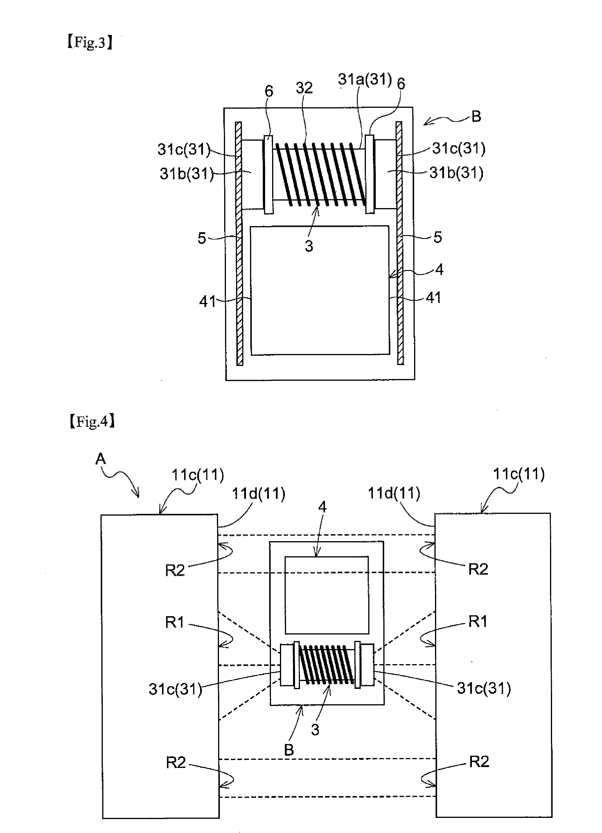
A noncontact power supply system includes a power supply device having a primary coil acting as an electromagnetic induction coil for a noncontact power supply system, and a power receiving device having a secondary coil. The primary coil has a primary core and a winding wire. The secondary coil has a secondary core and a winding wire. The primary core includes a base segment, a pair of extension segments, and a pair of opposite segments. The pair of opposite segments are arranged to allow a space to be defined therebetween. The winding wire is wound at least around the pair of opposite segments. The secondary coil is arranged between the pair of opposite segments during power supply. The power receiving device includes a magnetic sheet that is in tight contact with an end surface of the secondary core and has an area larger than that of the end surface.

Description

CROSS REFERENCE TO RELATED APPLICATIONS[0001]This application is based on and claims priority under 35 U.S.C. Section 119 to Japanese Patent Application No. 2013-144709 filed on Jul. 10, 2013 and No. 2013-144710 filed on Jul. 10, 2013, the entire content of which is incorporated herein by reference.TECHNICAL FILED[0002]This disclosure relates to a noncontact power supply system and an electromagnetic induction coil for a noncontact power supply apparatus.RELATED ART[0003]Conventionally, cordless electrical apparatuses such as mobile devices typically represented by mobile phones have a built-in rechargeable battery, in which battery charging is performed with a charging apparatus such as a cradle or an AC adaptor. Such a charging system allows a contact of the electrical apparatus to come into contact with a contact of the charging apparatus for electric conduction thereby to achieve power supply and battery charging.[0004]A noncontact power supply system is being employed these day...

Claims


Application Information

Patent Timeline
IPC IPC(8): H01F38/14H04B5/00
CPCH04B5/0037H01F38/14H01F30/16H01F3/10H02J50/10H04B5/79
Inventor OHTA, FUMIOEMA, HIROSHISATO, EIJI
Owner HOSIDEN CORP
Why Eureka
Try Eureka