Motor rotor with holes

Inactive Publication Date: 2019-08-15
NEW WIDETECH IND
View PDF3 Cites 0 Cited by
  • Summary
  • Abstract
  • Description
  • Claims
  • Application Information

AI Technical Summary

Benefits of technology

The present invention provides a motor rotor with holes that use two magnets to substitute one conventional curved magnet. This reduces the weight of the total magnets in the rotor, simplifies the manufacture, decreases the cost, and improves the efficiency of the motor by reducing vibration and noise. The arrangement of multiple first holes in the shape of a star increases the magnetic flux density, causing the magnetic flux density at a stator tooth to increase. This allows the smaller magnets to provide equal or higher magnetic flux density than the conventional curved magnet, reducing the total weight of magnets and cost of manufacturing the rotor. Additionally, the magnets arranged in the shape of a star increase the back electromotive force and reduce cogging torque, resulting in improved motor efficiency.

Problems solved by technology

First, a volume of each magnet 92 is big and a weight of each magnet 92 is heavy, so the cost is high as well.
However, the conventional structure of the rotor 91 and magnets 92 may increase the cogging torque, so the noise and vibration generated by the motor are significant.
Third, the curved magnet 92 with a curved surface is hard to be manufactured, so the cost of the motor is further higher.

Method used


Image

  • Motor rotor with holes
  • Motor rotor with holes
  • Motor rotor with holes

Examples


Embodiment Construction

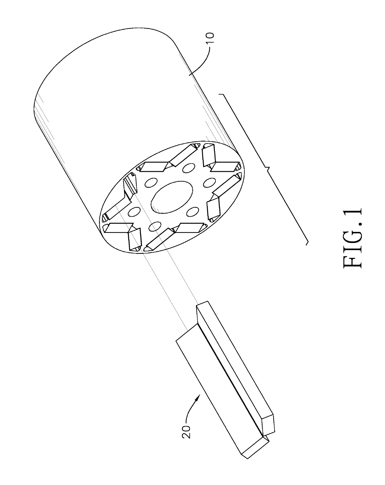
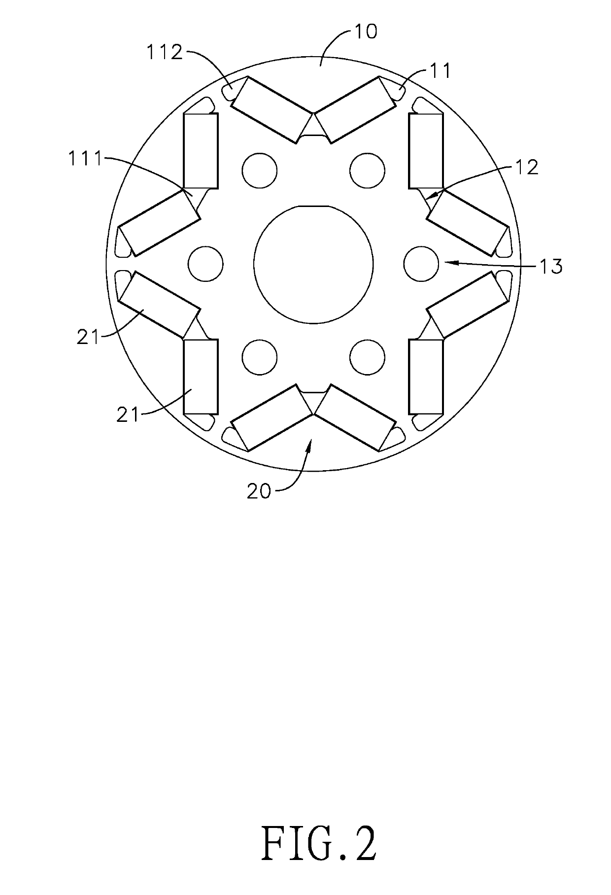
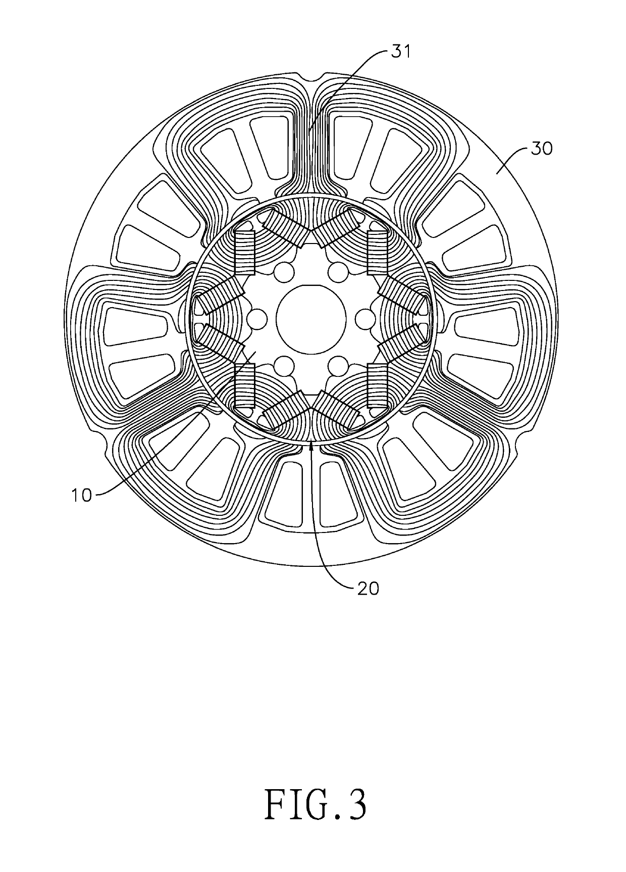
[0019]With reference to FIGS. 1 to 3, a rotor in accordance with the present invention is provided for a motor, and the rotor comprises a main body 10 and a plurality of magnet assemblies 20. During operation, the rotor is mounted in a stator 30 with an interval enclosing the rotor.

[0020]The main body 10 is, but not limited to, a cylinder. The main body 10 may not be a cylinder with a perfectly smooth surface, and an outer surface of the main body 10 may form multiple protrusions. In another embodiment, if the main body 10 can rotate in the stator 30 stably, the main body 10 may be in any shape, such as a polygonal column.

[0021]The main body 10 includes a plurality of first holes 11 formed through the main body 10. An axis of each one of the first holes 11 is parallel with a rotating axis of the main body 10. Each one of the first holes 11 integrally extends in a bending shape. The term “integrally” means when the rotor is viewed from a front view, each first hole 11 is a space with...


PUM


Abstract

A rotor for a brushless motor has a main body and multiple magnet assemblies. The main body has multiple first holes that extend in a bending shape. The first holes are arranged annularly and a bent corner portion of each first hole is closer to the rotation axis of the main body. Each magnet assembly has two magnets formed as a rectangular block and is mounted in one of the first holes. An angle is between the magnets and an air interval is formed between the magnets. With such a structure, a conventional curved magnet is substituted and magnetic lines of force are more concentrated, so a stator tooth can provide higher magnetic flux density. Especially, with the air interval, the magnetic flux leakage may be decreased. Consequently, even though the total weight of magnets is reduced, the efficiency of motor is still improved.

Description

BACKGROUND OF THE INVENTION1. Field of the Invention[0001]The present invention relates to a rotor for a motor, especially to a rotor including permanent magnets and used for a brushless motor.2. Description of the Prior Arts[0002]A brushless motor can convert electricity to kinetic energy with coils mounted on a stator and with permanent magnets mounted on a rotor. After energized with electricity, the coils generate magnetic fields and thus the permanent magnets can be driven to rotate through the variation of the magnetic fields.[0003]Please refer to FIG. 6. A conventional rotor 91 has a main body 911, a plurality of receiving holes 912 formed through the main body 911 in a lengthwise direction of the main body 911. The receiving holes 912 are annularly arranged apart from each other. Each one of the receiving holes 912 receives a curved magnet 92, and the curved magnet 92 is a permanent magnet. A side surface of each one of the curved magnets 92 far from a rotating axis of the m...

Claims


Application Information

Patent Timeline
IPC IPC(8): H02K1/27
CPCH02K1/2766H02K2213/03
Inventor CHIU, MING TSUNGCHIANG, JUI ANLIN, CHUNG MINGHSIEH, YAO YANG
Owner NEW WIDETECH IND
Why Eureka
Try Eureka