Method and magnetic resonance apparatus to determine a b0 field map

a magnetic resonance and field map technology, applied in the direction of reradiation, measurement using nmr, instruments, etc., can solve the problems of insufficient precision for small deviations from the nominal larmor frequency, ambiguities and errors in the calculation of b0 maps, etc., to achieve the effect of reducing the dynamic range of b1 amplitudes

Active Publication Date: 2015-01-15
SIEMENS HEALTHCARE GMBH
View PDF9 Cites 7 Cited by
  • Summary
  • Abstract
  • Description
  • Claims
  • Application Information

AI Technical Summary

Benefits of technology

[0031]In an embodiment of the invention, the excitation modes use more than one transmission channel, such that the dynamic range of the B1 amplitudes is reduced relative to the use of a single transmission channels. This means that those B1 mapping methods that limit the dynamic range of the B1 distribution (and therefore the amplitude signal variation) are particularly suitable for reliable determination of the B0 field map. This is efficiently achieved by—as has been explained—B1 field maps of different combinations of the transmission channels being acquired, and the B1 field maps of the transmission channels are computationally determined therefrom.

Problems solved by technology

This leads to ambiguities and errors in the calculation of the B0 maps.
The selection of extremely short dephasing times is frequently not possible due to the sequences that are used, and so smaller deviations from the nominal Larmor frequency can no longer be measured with sufficient precision given an extremely short echo time difference.
However, since the dynamic range of the B0 field distribution is not known before the measurement, the dephasing time must be chosen to be so short that the sensitivity of the acquisition method is not sufficient, and this procedure is consequently not used (as has already been explained).
However, the reliability of such algorithms is often questionable.
The primary difficulty exists in that the entire volume can be comprised of non-contiguous partial regions, such that individual partial regions of the B0 maps are separated by voxels that only include noise and are very low in signal.
However, the risk exists that a calculated B0 shim is optimized for false B0 offsets in different spatial areas.

Method used


Image

  • Method and magnetic resonance apparatus to determine a b0 field map
  • Method and magnetic resonance apparatus to determine a b0 field map
  • Method and magnetic resonance apparatus to determine a b0 field map

Examples


Embodiment Construction

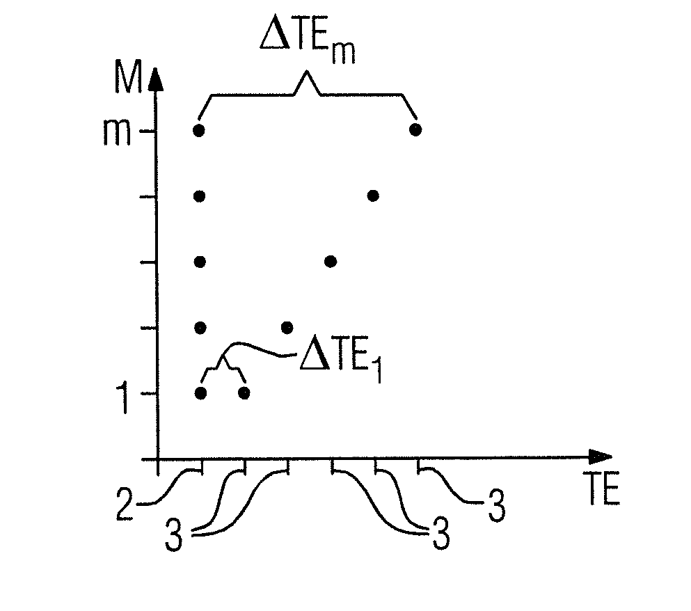
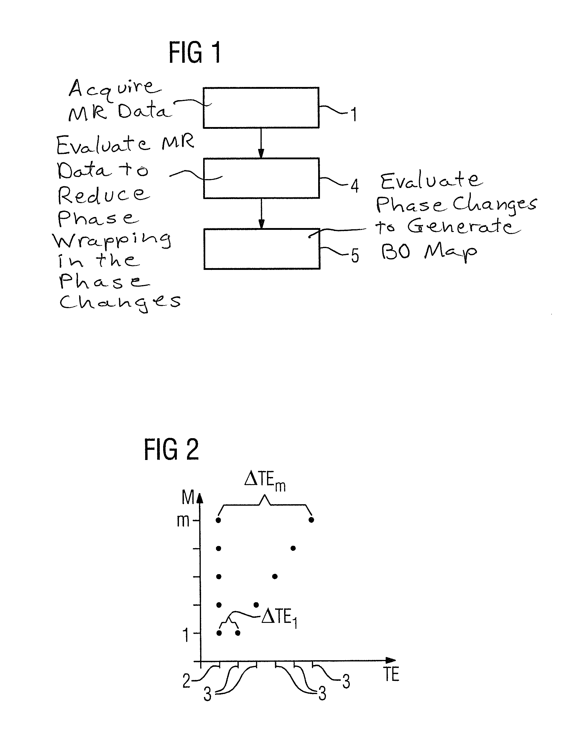
[0040]An exemplary embodiment of the method according to the invention is shown in FIG. 1. The basic goal is to qualitatively improve the determination of a B0 field map, wherein magnetic resonance data are based on different dephasing times, and the different dephasing times are used to resolve ambiguities due to Nyquist phase wrapping, in that different phase distributions are used as a starting point for different dephasing times (excitations generating different excitation fields are consequently used for different dephasing times). This can be realized particularly simply by acquiring the B0 field map together with B1 field maps, which is realized in the exemplary embodiment according to FIG. 1, and is implemented in step 1.

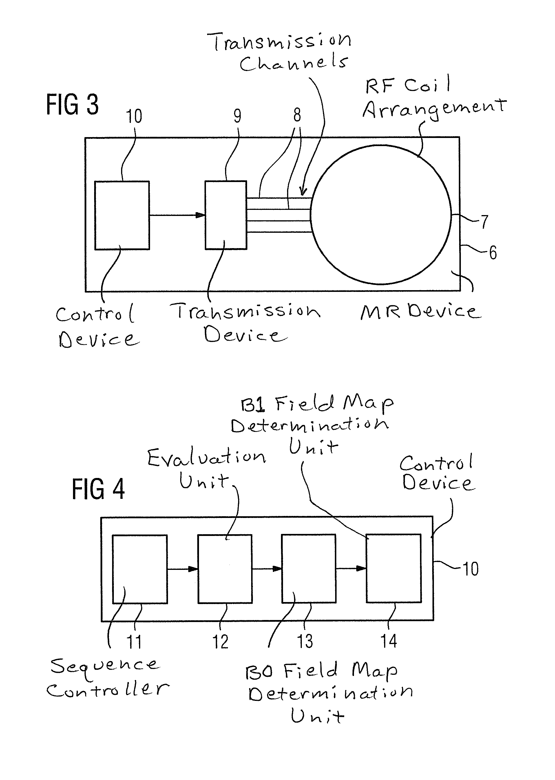
[0041]In accordance with the invention, n excitation modes are used, from the evaluation of which B1 field maps are then be calculated for the different transmission channels of a radio-frequency coil arrangement of the magnetic resonance device (as is known...


PUM


Abstract

In a method and magnetic resonance apparatus to determine a B0 field map describing the local deviation from a nominal Larmor frequency of the magnetic resonance apparatus, magnetic resonance data are acquired at at least two different dephasing times after an excitation, in measurements implemented at two different echo times whose difference forms a dephasing time, and a phase change used to determine the B0 field map is determined from a difference of phases measured at different echo times. The phase changes of different dephasing times are evaluated to at least partially reduce an ambiguity due to Nyquist phase wrapping. The measurements for different dephasing times are implemented at least in part with excitations that generate different excitation fields.

Description

BACKGROUND OF THE INVENTION[0001]1. Field of the Invention[0002]The present invention concerns a method to determine a B0 field map that describes the local deviation from a nominal Larmor frequency of a magnetic resonance device, wherein magnetic resonance data are acquired in measurements implemented at two different echo times whose difference forms a dephasing time, after an excitation at at least two different dephasing times; and a phase change to be used to determine the B0 field map is determined from a difference of phases measured at different echo times; wherein the phase changes of different dephasing times are evaluated for at least partially reducing an ambiguity due to Nyquist phase wrapping.[0003]2. Description of the Prior Art[0004]Magnetic resonance imaging and its basic operation are widely known in the prior art. A subject to be examined is introduced into a basic magnetic field with a relatively high field strength (known as the B0 field). In order to be able to...

Claims


Application Information

Patent Timeline
Patent Type & Authority Applications(United States)
IPC IPC(8): G01R33/44
CPCG01R33/443G01R33/243G01R33/56563
Inventor FAUTZ, HANS-PETER
Owner SIEMENS HEALTHCARE GMBH
Why Eureka
Try Eureka