
LCD and Backlight Module Thereof

Active Publication Date: 2015-01-15
SHENZHEN CHINA STAR OPTOELECTRONICS TECH CO LTD
View PDF11 Cites 3 Cited by
  • Summary
  • Abstract
  • Description
  • Claims
  • Application Information

AI Technical Summary

Benefits of technology

The present invention is about a liquid crystal display (LCD) with a backlight module that provides even distribution of light to display images. The backlight module has a diffuser plate and a plurality of optical fibers fixed between the diffuser plate and a back plate. The surface of the optical fibers has microstructures that evenly distribute light from the fibers. This invention ensures that ambient light is evenly distributed to the backlight module and guides it into the backlight module via the optical fibers.

Problems solved by technology

But, here is a problem to solve that how to effectively guide ambient light into a backlight module via optical fibers and ensure at the same time that the light is evenly distributed to a backlight module.

Method used


Image

  • LCD and Backlight Module Thereof
  • LCD and Backlight Module Thereof
  • LCD and Backlight Module Thereof

Examples


Embodiment Construction

[0032]The accompanying drawings are included to provide a further understanding of the invention, and are incorporated in and constitute a part of this specification. The drawings illustrate embodiments of the invention and, together with the description, serve to explain the principles of the invention.

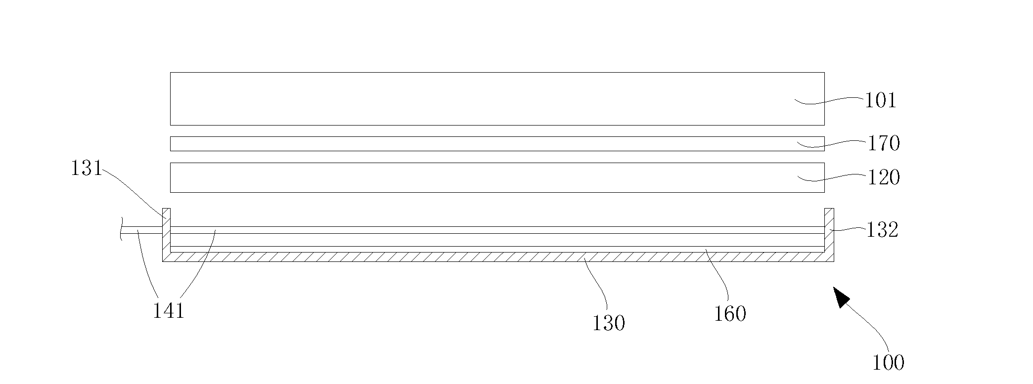
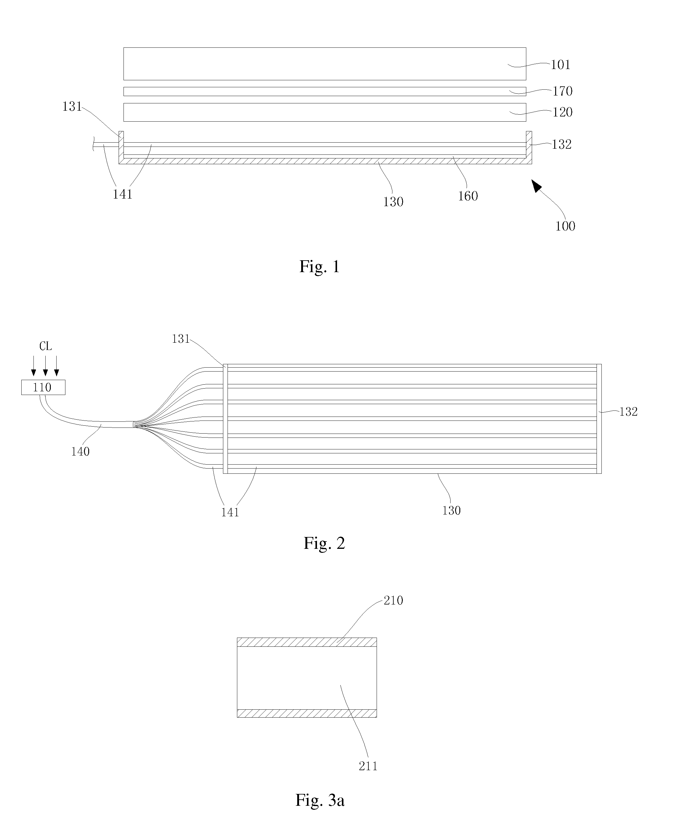
[0033]FIG. 1 is a diagram of an LCD of an embodiment according to the present invention. FIG. 2 is a diagram of a backlight module of an embodiment according to the present invention. In FIG. 2, it omits a diffuser plate, optical film and reflector sheet for conveninently showing connection of optical fibers between two side plates of a back plate.

[0034]Please refer to FIG. 1 and FIG. 2. A backlight module 100 of the embodiment according to the present invention is set up in opposition to an LCD panel 101 to form an LCD. The backlight module 100 provides a display light source to the LCD panel 101 for displaying images. The backlight module 100 comprises an ambient light collector 11...


PUM


Abstract

An LCD having a backlight module is proposed. The backlight module includes an ambient light collector for collecting ambient light; a back plate; a diffuser plate on the back plate; a plurality of optical fibers straightly fixed between the diffuser plate and the back plate and coupled to the ambient light collector. Microstructure is formed on the surface of the optical fibers straightly fixed between the diffuser plate and the back plate, and the microstructure makes light from the optical fibers evenly being emitted. The backlight module utilizes microstructure formed on a surface of optical fibers for evenly distributing light from the surface of the optical fibers. In hence, it effectively guides ambient light into the backlight module via the optical fibers and ensures at the same time that the light is evenly distributed to the backlight module.

Description

BACKGROUND OF THE INVENTION[0001]1. Field of the Invention[0002]The present invention relates to a liquid crystal display (LCD) field, more particularly, to an LCD using optical fibers as backlight sources and the backlight module thereof.[0003]2. Description of the Prior Art[0004]Conventionally, most of backlight modules in a liquid crystal display (LCD) takes an original light source, which illuminates by energy like electrical power, as a backlight source, for instance Light Emitting Diode (LED), Cold Cathode Fluorescent Lamp (CCFL), etc. The LED is broadly applied as a backlight source in a backlight module on account of its high power-saving. With more and more consciousness for power-saving and enviromental protection, a reduction of power consumption of a backlight source in a backlight module is necessary. Therefore, it needs to lessen a number of original light sources to reduce power consumption of a backlight source or takes a new-type energy-saving light source as a back...

Claims


Application Information

Patent Timeline
IPC IPC(8): G02F1/1335F21V8/00
CPCG02F1/133606G02B6/001G02B6/0008G02F1/1336G02F1/133618
Inventor FAN, YONGQIU, YONGYUANNING, CHAO
Owner SHENZHEN CHINA STAR OPTOELECTRONICS TECH CO LTD
Learn More