Speaker device, audio visual equipment, mobile information processing apparatus, vehicle, and earphone

a technology for audio visual equipment and earphones, which is applied in the direction of transducer details, electrical transducers, electrical apparatus, etc., can solve the problems of conventional techniques and limitations in downsizing and reproduction performance, and achieve the effects of wide frequency range, convenient mounting, and reduced siz

Active Publication Date: 2015-01-15
PANASONIC INTELLECTUAL PROPERTY MANAGEMENT CO LTD
View PDF11 Cites 18 Cited by
  • Summary
  • Abstract
  • Description
  • Claims
  • Application Information

AI Technical Summary

Benefits of technology

[0011]According to the speaker device of the present invention, a magnet having no hole can be used as the magnet constituting the magnetic circuit. Therefore, the speaker device can be downsized or slimmed without being restricted by problems in manufacturing, such as cracking during sintering. Accordingly, it is possible to provide a compact speaker device which is more easily mountable, and enables reproduction in a wide frequency range.

Problems solved by technology

However, since downsizing and sophistication are simultaneously progressing, devices mounted on each equipment are desired to be smaller and thinner.
However, downsizing of a speaker device causes degradation of reproduction performance, particularly, reproduction frequency band or reproduction efficiency, and therefore, conventional techniques have limitations in downsizing and reproduction performance.

Method used


Image

  • Speaker device, audio visual equipment, mobile information processing apparatus, vehicle, and earphone
  • Speaker device, audio visual equipment, mobile information processing apparatus, vehicle, and earphone
  • Speaker device, audio visual equipment, mobile information processing apparatus, vehicle, and earphone

Examples


embodiment 1

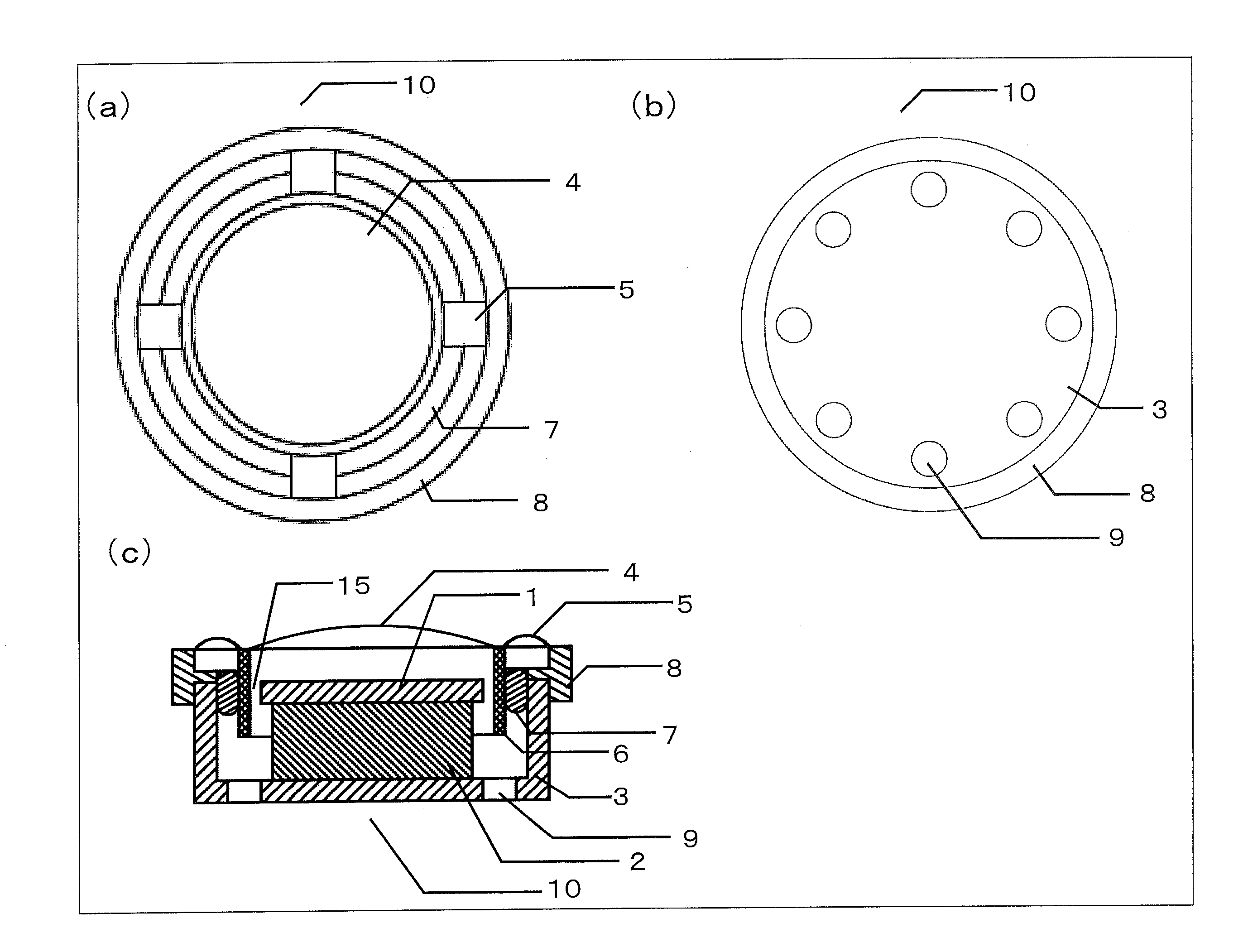
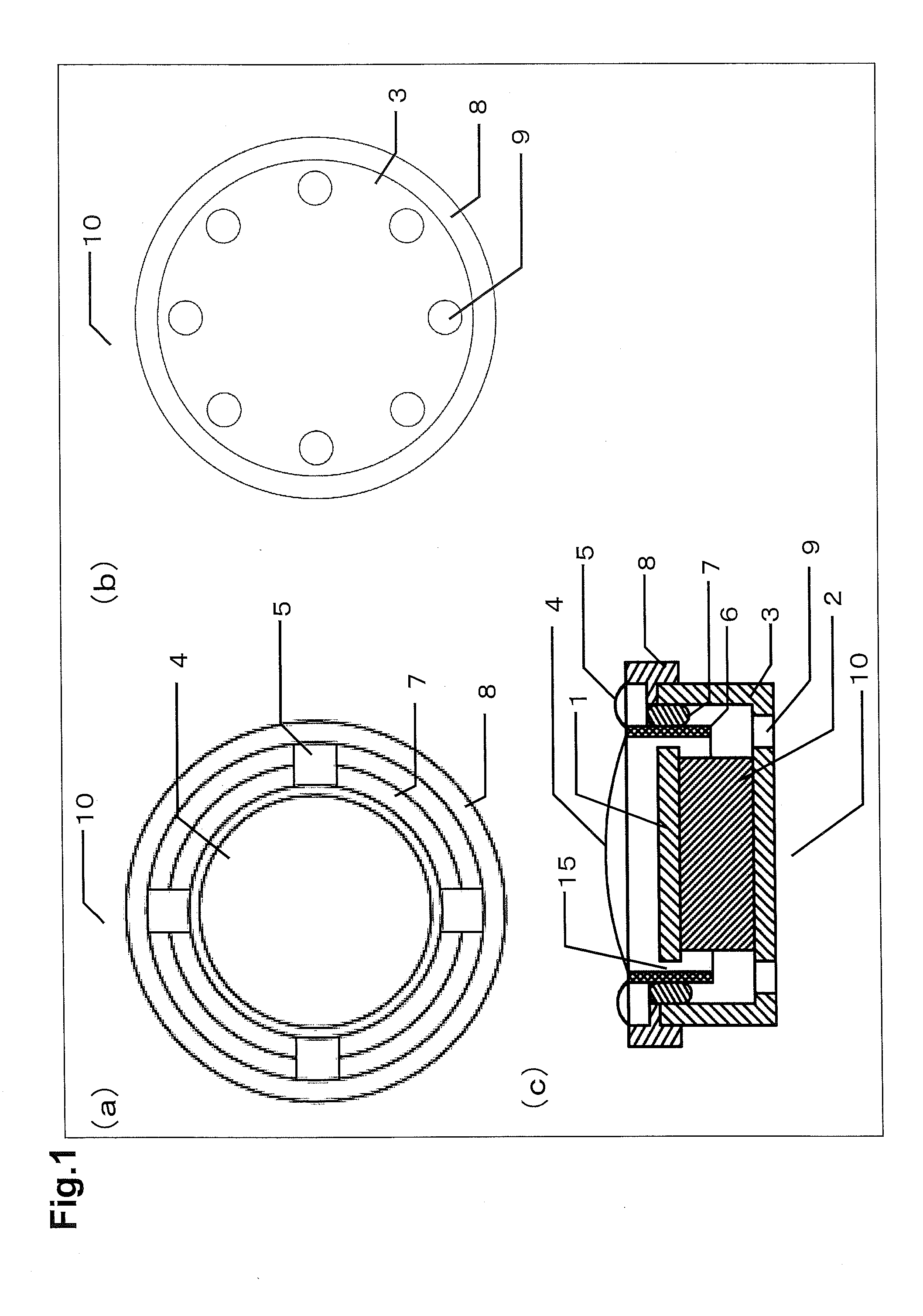
[0042]FIG. 1 shows a top view (FIG. 1(a)), a bottom view (FIG. 1(b)), and a structural cross-sectional view (FIG. 1(c)) of a coin type speaker device 10 according to Embodiment 1. The speaker device 10 includes a plate 1, a magnet 2, a yoke 3, a diaphragm 4, suspensions 5 (elastically deformable supporting members), a voice coil 6, a magnetic fluid 7, and a frame 8. The plate 1, the magnet 2, and the yoke 3 forms a magnetic circuit (a magnetic circuit of an internal magnetic type). A magnetic gap is formed between the plate 1 and the yoke 3. The voice coil 6 is located in the magnetic gap. The magnetic fluid 7 is disposed between the voice coil 6 and the yoke 3. The diaphragm 4 is supported by the frame 8 provided at an outer peripheral portion of the magnetic circuit, and the four suspensions 5 (supporting members) adhered to the diaphragm 4. At a bottom surface (bottom part) of the yoke 3, a plurality of through-holes 9 are formed in a region other than a region where the magnet 2...

embodiment 2

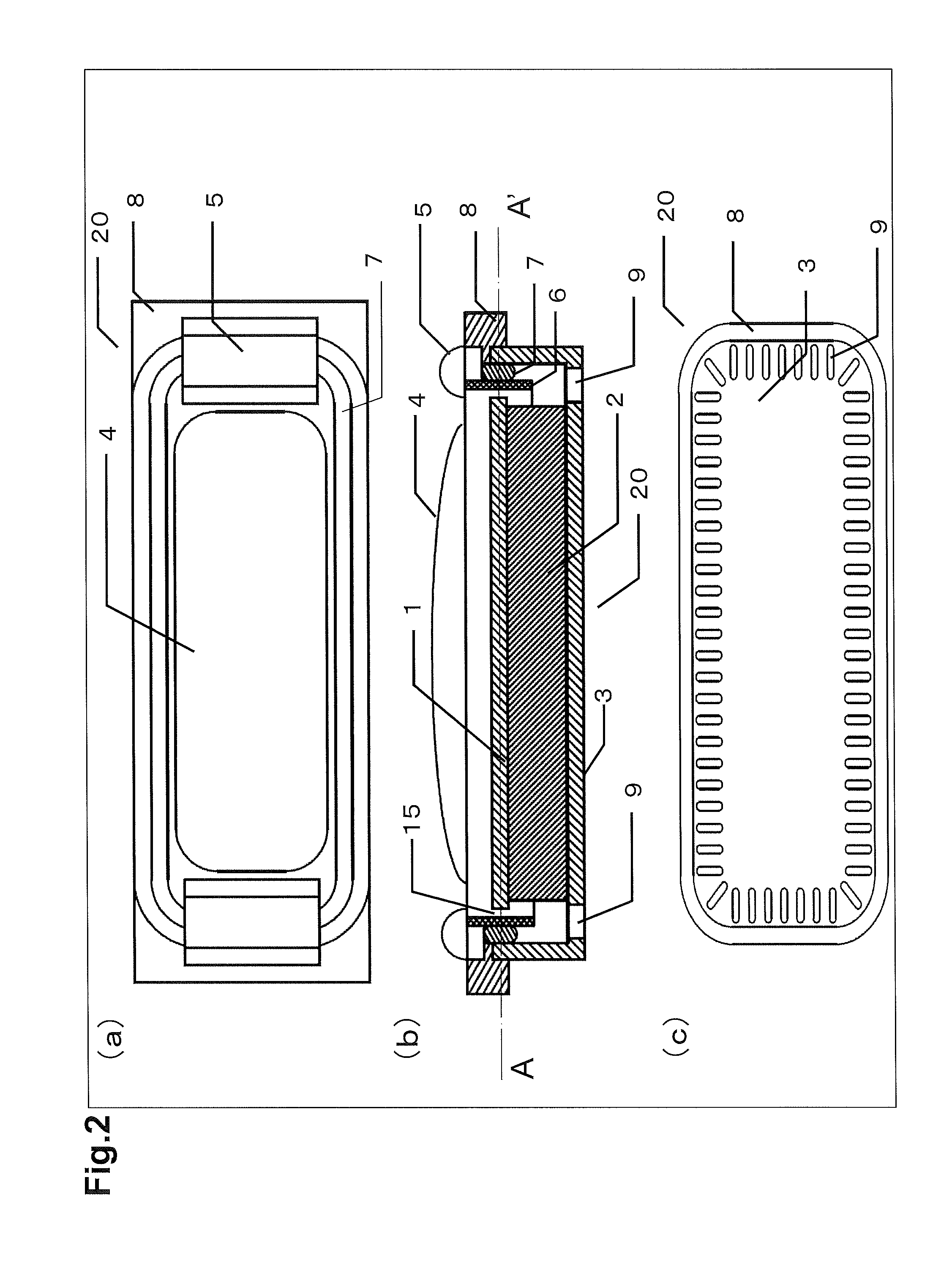
[0052]FIG. 2 shows a top view (FIG. 2(a)), a structural cross-sectional view (FIG. 2(b)), and a bottom view (FIG. 2(c)) of a speaker device 20 according to Embodiment 2. Since components included in the speaker device 20 shown in FIG. 2 are identical in function to the components included in the speaker device 10 according to Embodiment 1, description thereof will partially be omitted. The components of the speaker device 20 are denoted with the same reference numerals as those of the speaker device 10. The speaker device 20 is different from the speaker device 10 of Embodiment 1 in that the speaker device 20 has a rectangular shape while the speaker device 10 has a circular (coin) shape. Accordingly, the shapes of the components of the speaker device 20 are different from those of the speaker device 10 of Embodiment 1. In addition, while the number of the suspensions 5 is four in the speaker device 10 of Embodiment 1, in the speaker device 20, the diaphragm 4 is supported by two su...

embodiment 3

[0061]FIG. 4A shows a structural cross-sectional view (FIG. 4A(a)) and a side view (FIG. 4A(b)) of a speaker device 30 according to Embodiment 3. FIG. 4B shows a structural cross-sectional view (FIG. 4B(a)) and a side view (FIG. 4B(b)) of a speaker device 31 of a mode different from the speaker device 30 shown in FIG. 4A. Since components included in the speaker device 30 shown in FIG. 4A are identical in function to the components of the speaker device 10 according to Embodiment 1, description thereof will partially be omitted. The components of the speaker device 30 are denoted with the same reference numerals as those of the speaker device 10. The speaker device 31 shown in FIG. 4B includes a lead wire 11 (a wire drawn from the voice coil 6) in addition to the components of the speaker device 10.

[0062]Since the operation of the speaker device is identical to that of Embodiment 1, repeated description is not necessary.

[0063]The speaker device 30 and the speaker device 31 are diffe...


PUM


Abstract

A speaker device includes: a magnetic circuit including a plate 1, a magnet 2 having no through-hole, and a yoke 3 forming a magnetic gap; a voice coil 6 disposed in the magnetic gap; a diaphragm 4 directly or indirectly fixed to the voice coil 6; and a magnetic fluid 7 disposed in at least a space between an outer peripheral surface of the voice coil 6 and an inner peripheral surface of the yoke 3. A rear surface side space between a rear surface of the diaphragm 4 and a front surface of the plate 1 communicates with a space outside the speaker device through a gap-for-communication 15 which is formed in at least a part, in a peripheral direction of the voice coil 6, of the space between the outer peripheral surface of the plate 1 and the inner peripheral surface of the voice coil 6.

Description

TECHNICAL FIELD[0001]The present invention relates to speaker devices, audio visual equipment including speaker devices, mobile information processing apparatuses including speaker devices, vehicles including speaker devices, earphones including speaker devices, and the like.BACKGROUND ART[0002]In recent years, downsizing and sophistication of audio visual devices, i.e., so-called AV equipment, are rapidly progressing. Downsizing and sophistication are particularly remarkable in cellular phones, smartphones, tablet PC (personal computer) terminals, and the like. However, since downsizing and sophistication are simultaneously progressing, devices mounted on each equipment are desired to be smaller and thinner. Speaker devices mounted on each equipment are no exception, and are desired to be smaller and thinner like other devices. However, downsizing of a speaker device causes degradation of reproduction performance, particularly, reproduction frequency band or reproduction efficiency...

Claims


Application Information

Patent Timeline
Patent Type & Authority Applications(United States)
IPC IPC(8): H04R9/02
CPCH04R9/027H04R7/18H04R9/06H04R2499/11
Inventor MATSUMURA, TOSHIYUKISAIKI, SHUJI
Owner PANASONIC INTELLECTUAL PROPERTY MANAGEMENT CO LTD
Why Eureka
Try Eureka