
Dental implant with high combining stability

Inactive Publication Date: 2015-01-15
TAIWAN SHAN YIN INT CO LTD
View PDF12 Cites 11 Cited by
  • Summary
  • Abstract
  • Description
  • Claims
  • Application Information

AI Technical Summary

Benefits of technology

The present invention is about a dental implant with high combining stability that increases the feel and stability of the implant. It has a shank with a threaded section that is securely embedded in the alveolar bone, which helps to prevent the implant from being pulled out during mastication. The dental implant has a small diameter at the connecting part, which makes it easy to fasten and secure in place. The invention improves the efficiency and stability of the dental implant during implantation.

Problems solved by technology

However, some problems still exist in the conventional design.
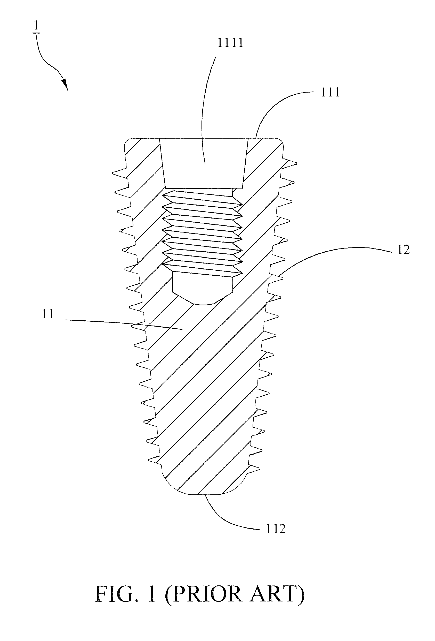
Due to the taper-shaped shank and the pre-drilled bore on the alveolar bone, the wall of the bore and the threaded portion 12 at the front and middle parts of the shank 11 are not well contacted, which leads to a poor feel of fastening the dental implant of the dentist and a poor stability of the initial implanting status.

Method used


Image

  • Dental implant with high combining stability
  • Dental implant with high combining stability
  • Dental implant with high combining stability

Examples


Embodiment Construction

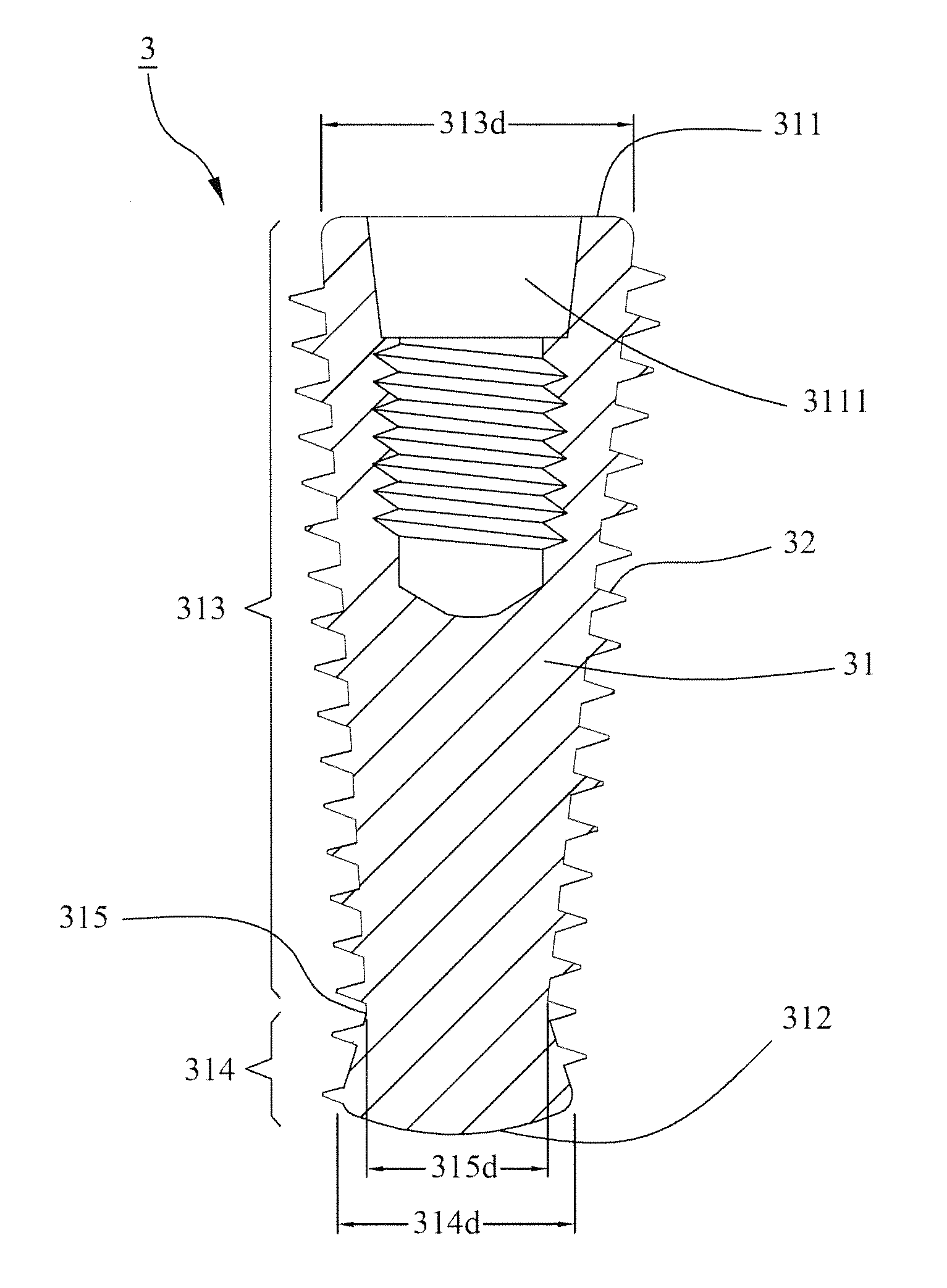
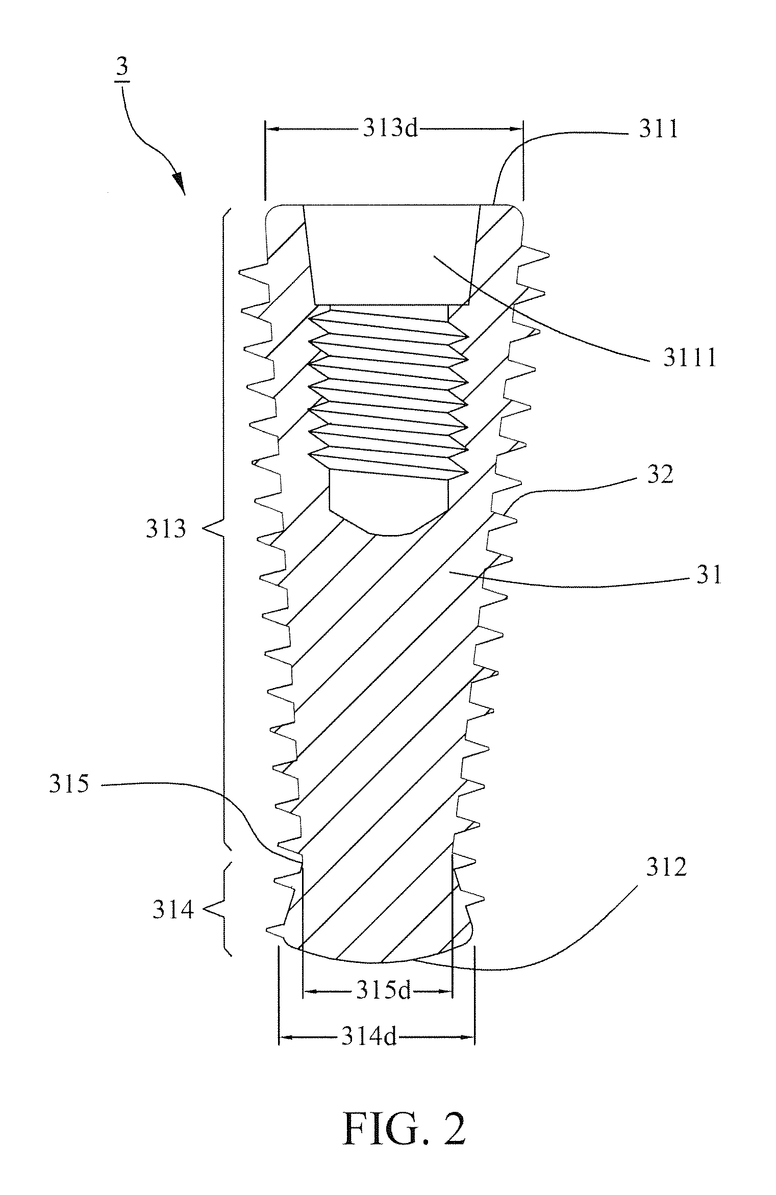
[0019]Referring to FIG. 2 shows a first preferred embodiment of a dental implant 3 with high combining stability of the present invention. The dental implant 3 comprises a shank 31 and a threaded section 32 spirally disposed on the shank 31. Wherein, a first end 311 and a second end 312 opposite to the first end 311 are respectively formed at two sides of the shank 31. The shank 31 further includes a first section 313 extending from the first end 311 toward the second end 312 and a second section 314 connecting the first section 313 and extending to the second end 312. The first section 313 and the second section 314 are connected at a connecting part 315, and a shank diameter 315d of the connecting part 315 is smaller than a shank diameter 314d of the second section 314. In this preferred embodiment, a shank diameter 313d of the first section 313 is gradually decreased toward a direction of the second section 314, and a shank diameter 314d of the second section 314 is gradually inc...


PUM


Abstract

A dental implant comprises a shank and a threaded section spirally disposed on the shank. The shank includes a first section extending from a first end toward a second end of the shank and a second section connecting the first section and extending to the second end. A shank diameter of a connecting part where the first and the second sections are connected is smaller than that of the second section, whereby the subject configuration increases an implant-fastening feel of dentists and an initial implanting stability efficiently while implanting the dental implant into an alveolar bone. When the dental implant is enclosed by a growth of the bone, the second section is firmly fixed by the bone to prevent the dental implant from loosening due to an inverse torque derived from the mastication and allow it to be firmly embedded in the bone to increase the combining stability.

Description

BACKGROUND OF THE INVENTION[0001]1. Field of the Invention[0002]The present invention relates to a dental implant, particular to a dental implant with high combining stability for being implanted into the alveolar bone of the human body.[0003]2. Description of the Related Art[0004]Referring to FIG. 1, a conventional dental implant includes a shank 11 and a threaded portion 12 spirally disposed on the shank 11. Wherein, a first end 111 and a second end 112 opposite to the first end 111 are respectively defined on two sides of the shank 11. A slot 1111 is formed on the first end 111 to allow an abutment (not shown) to install and fix thereon. The second end 112 is formed into an arch shape. Further, the shank diameter of the shank 11 is gradually decreased from the first end 111 to the second end 112. In an implanting operation, the dental implant 1 is firstly put into a bore pre-drilled on an alveolar bone. Then, the second end 112 is applied to separate the gums and nerves in the vi...

Claims


Application Information

Patent Timeline
IPC IPC(8): A61C8/00
CPCA61C8/0025A61C8/0045
Inventor SU, KOU-TSAIRSU, YU-JUNG
Owner TAIWAN SHAN YIN INT CO LTD
Learn More