Aortic cross clamp

a cross-clamp and aortic technology, applied in the field of cross-clamps, can solve the problems that minimally invasive techniques have made traditional cross-clamps less desirable, and achieve the effect of reducing the trauma to the aorta

Active Publication Date: 2015-01-15
CORCYM SRL
View PDF16 Cites 11 Cited by
  • Summary
  • Abstract
  • Description
  • Claims
  • Application Information

AI Technical Summary

Benefits of technology

[0010]The jaws can comprise flexible engagement pads for reducing trauma to the aorta when

Problems solved by technology

Increasingly, minimally invasive techniques hav

Method used


Image

  • Aortic cross clamp
  • Aortic cross clamp
  • Aortic cross clamp

Examples


Embodiment Construction

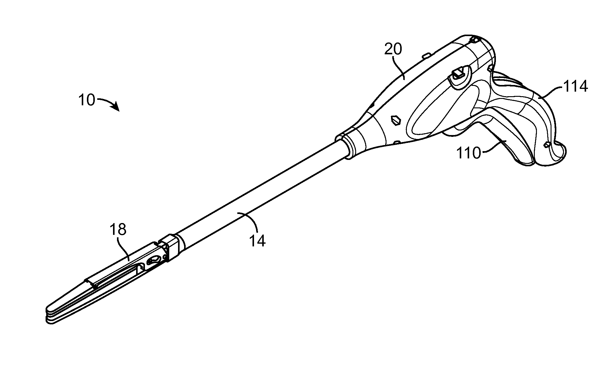
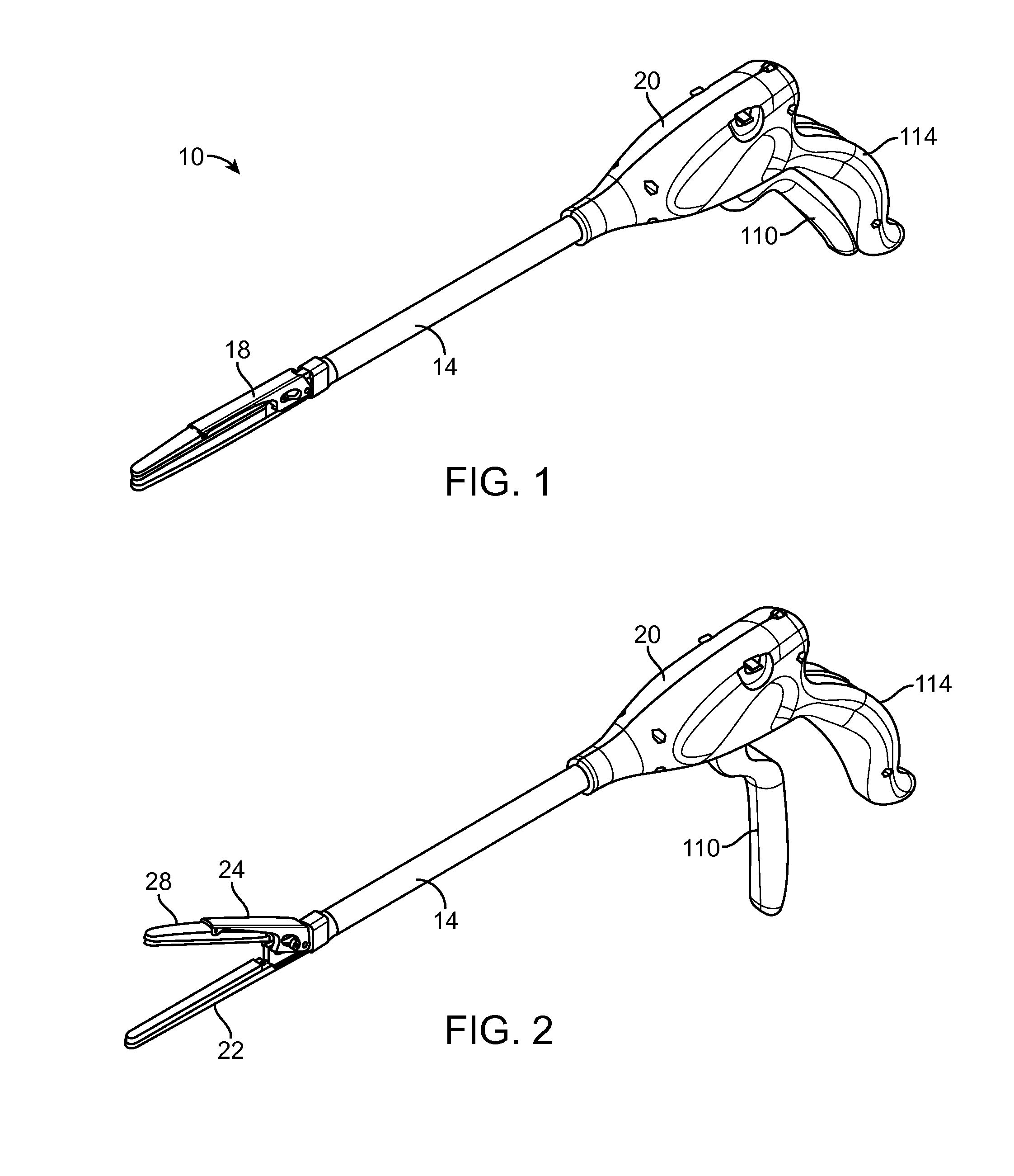
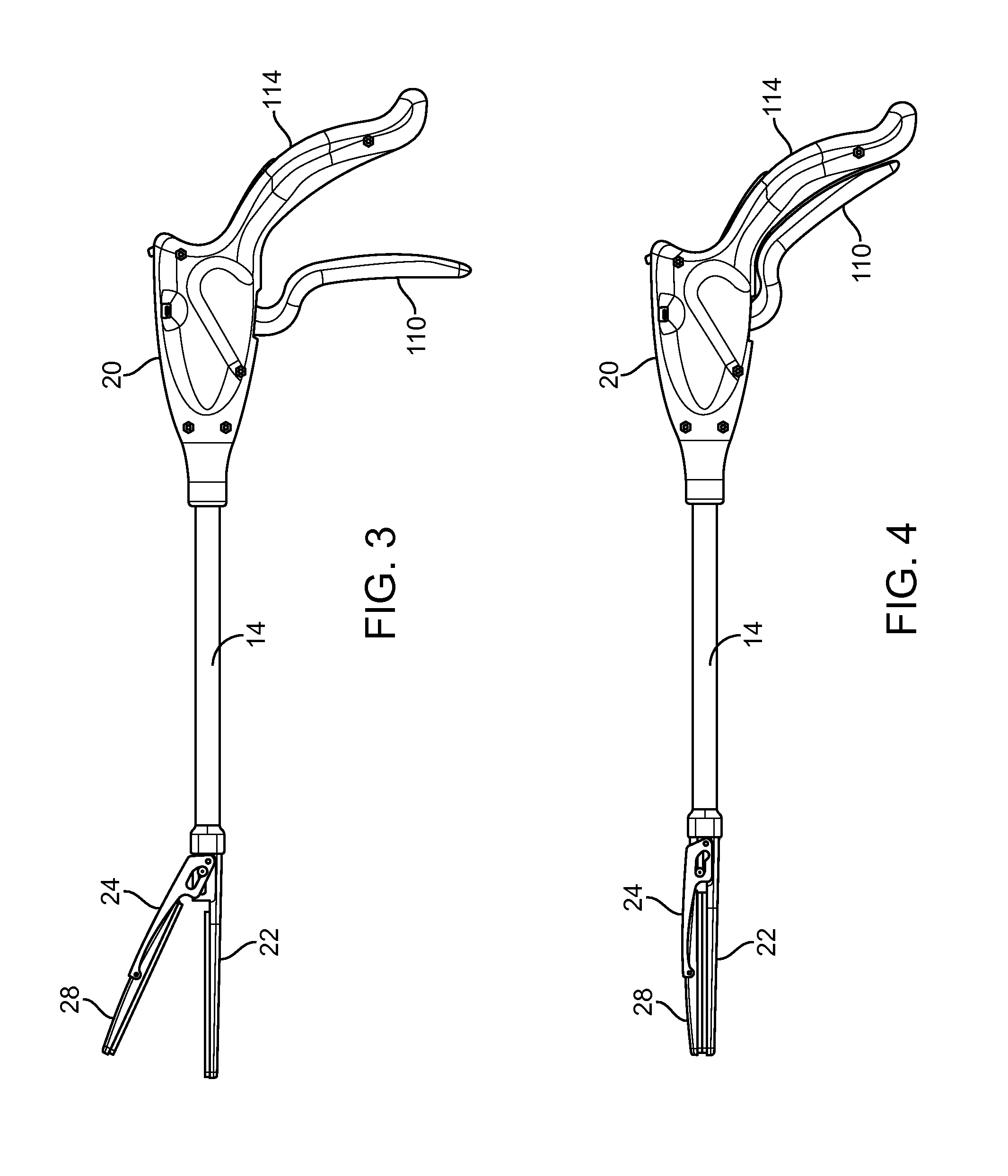
[0046]There is shown in the drawings an aortic cross clamp 10 according to one embodiment of the invention. The aortic cross clamp 10 includes an elongated handle 14 and a clamp head 18. The clamp head 18 has opposing jaws 22 and 28 having open and closed positions. At least one of the jaws is pivotally mounted to a jaw actuator 24 so as to be pivotal relative to the opposing jaw and about an axis distanced from the opposing jaw. This axis is also substantially transverse to the long dimension of the jaws. A locking mechanism is provided for locking the jaws in the closed position. A jaw drive mechanism is operable through the elongated handle 14 for moving the jaws between open and closed positions. In one embodiment the elongated handle 14 is connected to a handle grip 20.

[0047]The jaw 28 can be pivotally mounted to jaw actuator 24 by any suitable structure, such as a pivot pin 30. The pivot pin 30 permits rotation about the axis distanced from the opposing jaw 22. In this manner,...


PUM


Abstract

An aortic cross clamp includes an elongated handle and a clamp head. The clamp head has opposing jaws having open and closed positions. At least one of the jaws is pivotally mounted to a jaw actuator so as to be pivotal relative to the opposing jaw and about an axis distanced from the opposing jaw. A locking mechanism is provided for locking the jaws in the closed position. A jaw drive mechanism is operable through the elongated handle for moving the jaws between the open and closed positions. A method of clamping the aorta is also disclosed.

Description

FIELD OF THE INVENTION[0001]This invention relates to cross clamps, and more particularly to aortic cross clamps.BACKGROUND OF THE INVENTION[0002]Cross clamps are used in heart surgery to clamp the aorta. Increasingly, minimally invasive techniques have made traditional cross clamps less desirable. There is a need for aortic cross clamps which are suited for minimally invasive surgical techniques, either applied through a port or cannula or through a small incision.SUMMARY OF THE INVENTION[0003]An aortic cross clamp includes an elongated handle and a clamp head. The clamp head has opposing jaws having open and closed positions. At least one of the jaws is pivotally mounted to a jaw actuator so as to be pivotal relative to the opposing jaw and about an axis distanced from the opposing jaw. A locking mechanism is provided for locking the jaws in the closed position. A jaw drive mechanism is operable through the elongated handle for moving the jaws between the open and closed positions...

Claims


Application Information

Patent Timeline
IPC IPC(8): A61B17/122
CPCA61B17/128A61B17/122A61B17/1285A61B17/29A61B2017/00473A61B2017/00778A61B2017/2808A61B2017/2825A61B2017/2916A61B2017/2931A61B2017/2936
Inventor POO, RAMONLAMELAS, JOSEPH
Owner CORCYM SRL
Why Eureka
Try Eureka