Multi-lumen catheter

a catheter and lumen technology, applied in the field of multi-lumen catheters, can solve the problems of stagnant blood voids, unsuitable for prolonged placement, stiff tips, etc., and achieve the effect of minimizing the recirculation of treated blood and facilitating blood exchang

Active Publication Date: 2009-08-04
AEGIS MEDICAL TECH
View PDF40 Cites 109 Cited by
  • Summary
  • Abstract
  • Description
  • Claims
  • Application Information

AI Technical Summary

Benefits of technology

[0022]Another object is to provide a multi-lumen catheter which is capable of accommodating high flow rates.
[0024]Still another object is to provide a multi-lumen catheter which permits high flow rates while reducing trauma to vessel walls and red cell damage.
[0025]Yet another object of the present invention is a multi-lumen catheter having a tip configuration which minimizes recirculation by maximizing the control and direction of blood flow into and out from the lumen ports.
[0027]In one embodiment, the change in direction of the flow pattern into and out of the catheter body is substantially helical. In other embodiments, the direction of the flow pattern into and out of the catheter body is curved, and in still other embodiments the direction of the flow pattern into and out of the catheter body is angled. In this manner, the flow patterns of these embodiments provide for more efficient exchange of blood by creating an alternate pattern of blood dynamics through the catheter lumina and the vessel.
[0028]In another embodiment, the ports of the lumina are longitudinally spaced. In this manner the withdrawal of blood to be treated and the return of treated blood are further separated so as to advantageously minimize the recirculation of treated blood with untreated blood. The length of separation may vary according with specific application, and is preferably from about 2 to about 3 centimeters. Preferably, the lumen port associated with the withdrawal of blood from the patient is “upstream” of the lumen port associated with the return of treated blood.

Problems solved by technology

Although this particular form of catheter has not achieved significant success in the marketplace, it was the forerunner of dual-lumen catheters implanted in the subclavian vein for periodic hemodialysis.
This has led to other problems such as very stiff tips which are unsuitable for prolonged placement in a vein; voids which can accumulate stagnant blood; and short stubby tips which are less desirable for insertion than longer more gradual tips.
Also, because there is not always sufficient material to form the tip, plugs have been added with a varying degree of success because if the plug is not placed accurately the resulting structure may have unacceptable spaces where blood can stagnate.
In such circumstances it is possible that a stiff tip could damage or even embed itself in the vessel wall when left in place for extended periods.
However, problems occur with both the line introducing purified blood back into the vein and the line removing blood for purification at flow rates above 300 ml per minute.
A high flow rate from the venous line may cause whipping or “firehosing” of the tip in the vein with consequent damage to the vein lining.
A corresponding high flow rate into the arterial line may cause the port to be sucked into the vein wall, resulting in occlusion.
Thus, firehosing frequently results.
Firehosing may damage the vein wall, triggering the build-up of fibrin on the catheter tip.
Fibrin build-up may further result in port occlusion.
However, such catheters have not been entirely successful in solving problems related to hemodialysis with dual lumen catheters, e.g., high incidences of catheter port occlusion as well as some degree of fire-hosing.
Further, the abrupt change in direction of the flow of blood from the vein into the catheter can result in trauma and damage to red blood cells, especially at higher flow rates.

Method used


Image

  • Multi-lumen catheter
  • Multi-lumen catheter
  • Multi-lumen catheter

Examples


Embodiment Construction

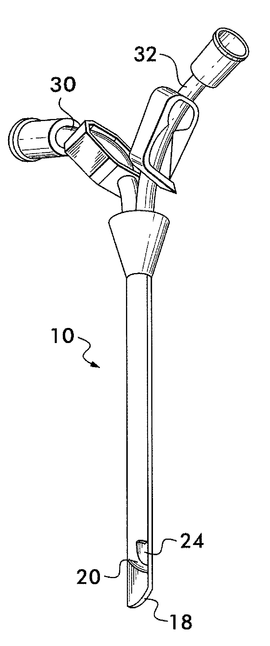
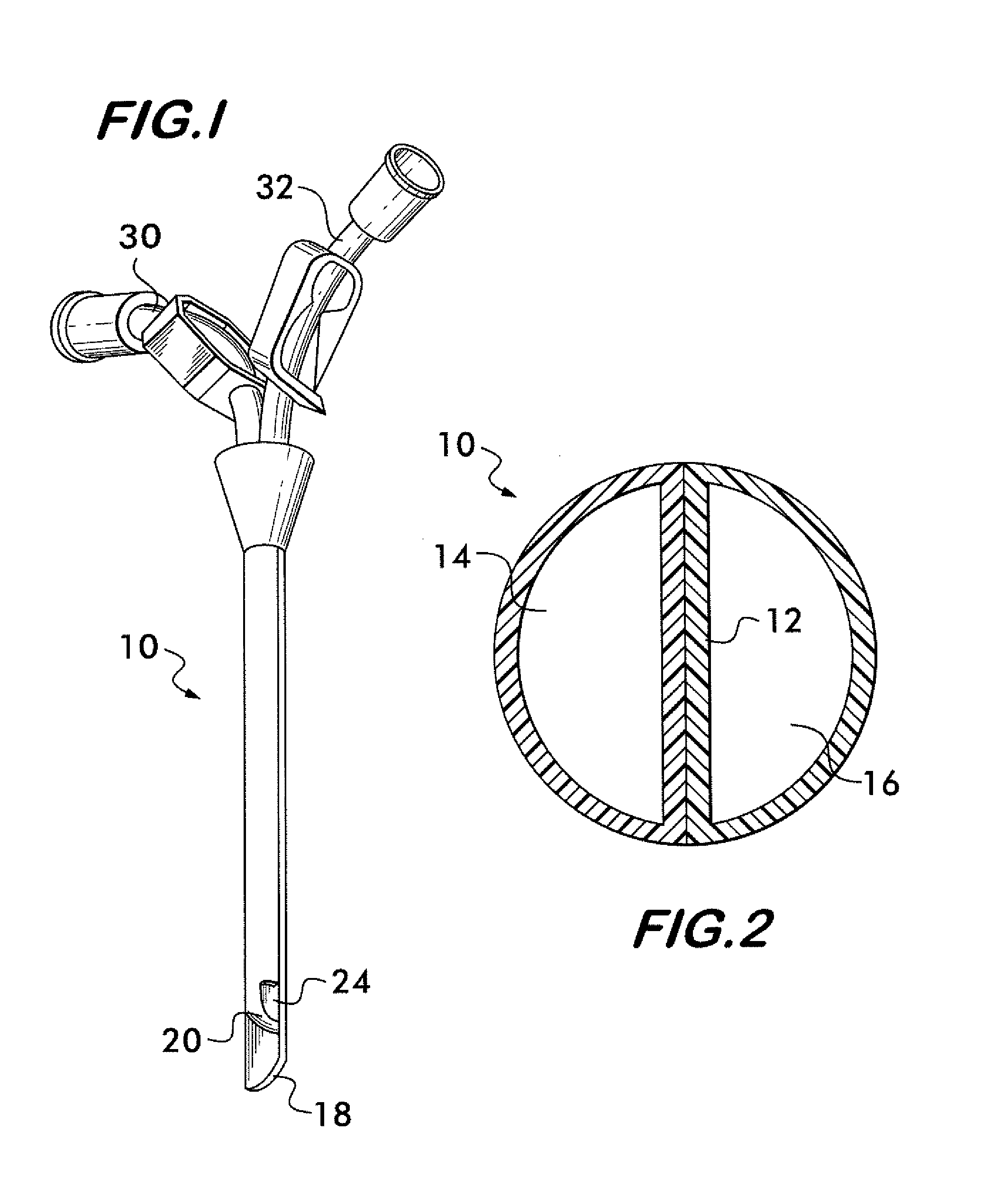
[0036]In accordance with the apparatus of the present invention, there is provided a catheter body that is adapted for insertion into a vessel of a patient such as, for example, a vein. The catheter body comprises an external wall and a septum extending longitudinally along the internal length of the catheter body to define two substantially parallel lumina each having an internal wall and a port located at the side of the distal end thereof.

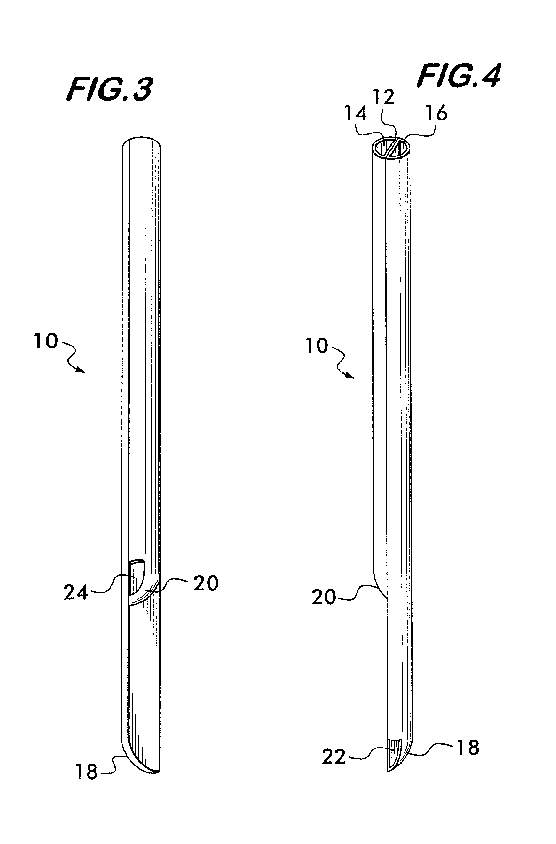
[0037]At the distal end of each lumen, at least a portion of the internal walls of the lumina are curved or angled to define a transition zone terminating at the port. So configured, the transition zone permits the flow of fluids traveling the length of the lumen to be gradually deflected from the longitudinal direction of the lumen to the transverse direction of the side-facing port at the distal end thereof.

[0038]For fluids entering the side-facing port of the lumen, the transition zone permits the flow to be gradually deflected from the direc...


PUM


Abstract

The invention provides a catheter for placement within a vessel of a patient. The catheter comprises an elongated catheter body, a septum extending longitudinally through the interior of the catheter body from the dividing the interior of the catheter body into a first lumen and a second lumen. Each lumen has curved or angled internal walls at the distal end of the catheter that terminate at ports located on opposing sides of the catheter body. The invention also provides a method for exchanging fluids in a patient comprising the step of positioning the catheter of the present invention in communication with a fluid-containing vessel of a patient. The method is particularly well-suited for hemodialysis, plasmapheresis, and other therapies which require removal and return of blood from a patient.

Description

CROSS-REFERENCE TO RELATED APPLICATION[0001]This application claims the benefit of U.S. Provisional Application No. 60 / 561,430, filed on Apr. 12, 2004, which is incorporated herein in its entirety.FIELD OF THE INVENTION[0002]The present invention relates to a multi-lumen catheter, and more specifically, a dual-lumen catheter with entry and exit ports having curved or angled walls to direct the flow of fluids therethrough.BACKGROUND OF THE INVENTION[0003]Dual-lumen catheters have been available for many years for a variety of medical purposes. It is only in recent years, however, that such catheters have been developed for use in hemodialysis and other treatments which involve the removal and replacement of blood. The general form of dual-lumen catheters goes back to as early as 1882 when Pfarre patented such a catheter in the United States under Ser. No. 256,590. This patent teaches a flexible dual-lumen catheter which is used primarily for cleaning and drainage of, for example, the...

Claims


Application Information

Patent Timeline
Patent Type & Authority Patents(United States)
IPC IPC(8): A61M3/00A61M1/36A61M25/00
CPCA61M25/0023A61M1/3661A61M2025/0031A61M2025/0037A61M2025/0034
Inventor CLARK, TIMOTHY W. I.
Owner AEGIS MEDICAL TECH
Why Eureka
Try Eureka