Expandable introducer system and methods

a technology of introducer and expandable body, which is applied in the direction of prosthesis, surgical forceps, ligaments, etc., can solve the problems of degenerative disc disease and lower back pain, other tissue damaged to create the pathway is not necessarily repaired or reconstructed, and tissue damage to a point where it may not function properly, etc., to achieve the effect of improving healing

Active Publication Date: 2011-03-10
P TECH
View PDF109 Cites 141 Cited by
  • Summary
  • Abstract
  • Description
  • Claims
  • Application Information

AI Technical Summary

Benefits of technology

[0026]In addition, there is provided a method for total disc replacement. An incision is made through tissue for access to the spine. The dimensions of the incision may be minimized to reduce trauma to surrounding tissue like muscle, ligaments, tendons, and cartilage. The vertebra located superior to the damaged disc being replaced is cut. The cut may be made on the lower or bottom portion of the superior vertebra. The cut may be planar or multiplanar. The superior vertebra may be cut without disturbing or at least minimally disturbing the adjacent ligaments, cartilage, and muscles. The cut may be angled to avoid damaging or loosening the spinal ligaments like the anterior and posterior longitudinal ligaments.

Problems solved by technology

In doing so, this tissue is damaged to a point where it may not function properly.
Currently, however, the other tissue like the muscles, ligaments, tendons, cartilage, bones, etc. which were damaged to create the pathway are not necessarily repaired or reconstructed.
For example, following spinal surgery, a frequent complication is late instability where there is shearing antero-posteriorly or superior inferiorly due to excess motion because the ligaments have been damaged during surgical exposure.
This complication may lead to degenerative disc disease and lower back pain.

Method used


Image

  • Expandable introducer system and methods
  • Expandable introducer system and methods
  • Expandable introducer system and methods

Examples


example 1

Intervertebral Disc Repair

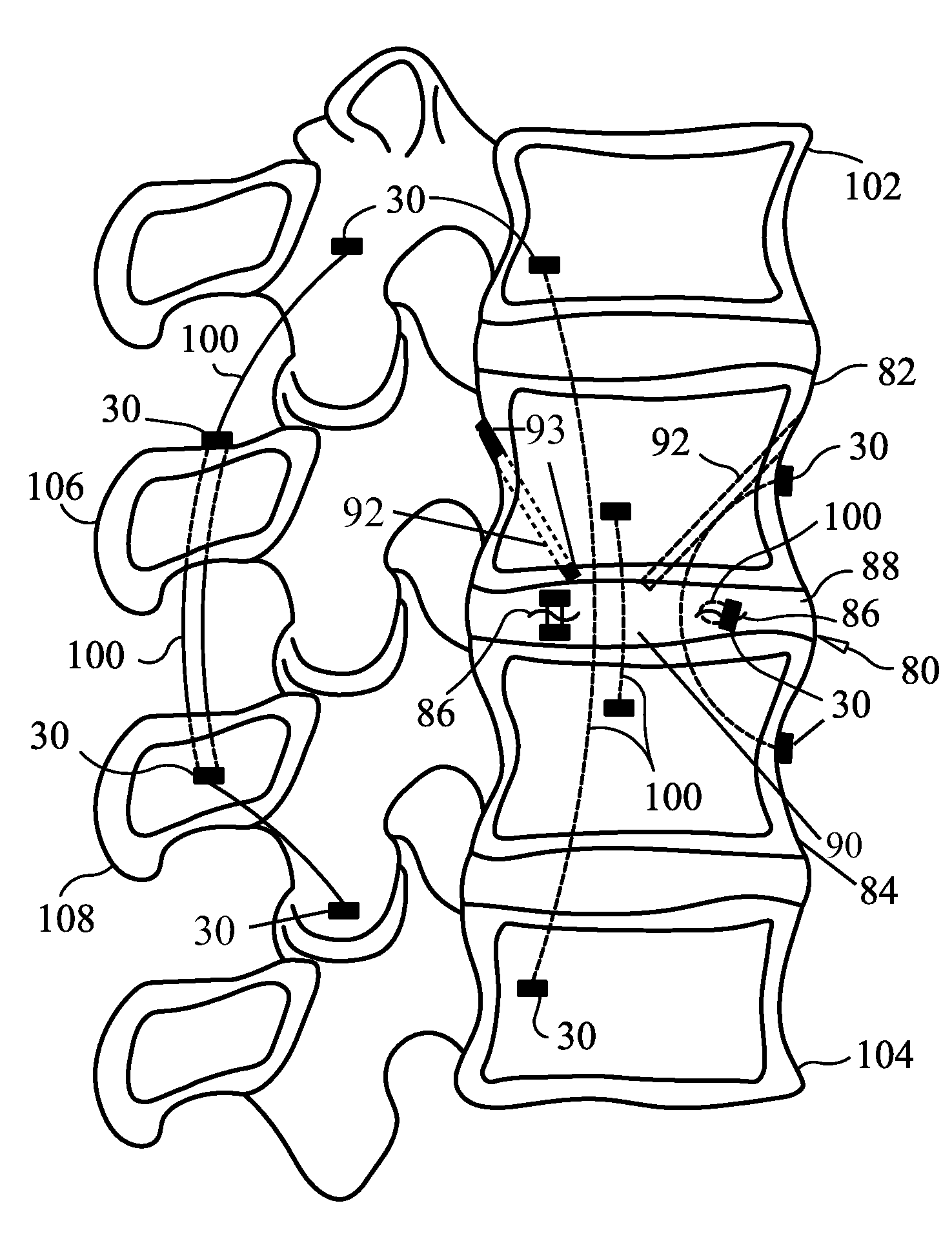
[0082]As previously described, the present invention provides devices and methods for fastening body tissue and / or an implant. One example is the fastening or repair of ligamentous tissue. Ligamentous tissue is found, among other locations, within intervertebral discs of the spinal column. The spinal column is formed from a number of vertebrae which are separated from each other by intervertebral discs. The intervertebral discs stabilize and distribute force between the many vertebrae. As used herein, “spinal joint” or joint of the spine includes this intervertebral space.

[0083]Generally, intervertebral discs are made of a soft, central nucleus pulposus surrounded by a tough, woven annulus fibrosus. Herniation of a disc is a result of a weakening in the annulus. Symptomatic herniations occur when weakness in the annulus allows the nucleus pulposus to bulge or leak posteriorly toward the spinal cord and major nerve roots. One treatment of a herniated, displa...

example 2

Intervertebral Disc Replacement

[0094]A damaged intervertebral disc may require replacement instead of just minor repair. The disc may be replaced with a prosthetic disc which may include a biocompatible material such as metal, polymer, composite, ceramic, or combinations thereof. FIG. 4 illustrates a total intervertebral disc replacement using the devices and methods of the present invention. While a disc replacement is shown and described below, it is contemplated that any skeletal region, like a joint, may be fitted with an implant, and the implant fastened and stabilized with the sutures, fasteners, and methods disclosed herein and incorporated by reference. For example, a knee replacement component may be affixed to the femur, tibia, or patella in accordance with the following described methods.

[0095]A disc replacement component may be positioned between the lower surface of a superior vertebra and the upper surface of an inferior vertebra. In this configuration, the disc replac...

example 3

Implant Anchoring

[0105]The devices and methods of the present invention may be further used to stabilize an implant positioned within the body. In addition to the type of implants previously mentioned, the implant may be an organ, partial organ grafts, tissue graft material (autogenic, allogenic, xenogenic, or synthetic), a malleable implant like a sponge, mesh, bag / sac / pouch, collagen, or gelatin, or a rigid implant made of metal, polymer, composite, or ceramic. Other implants include breast implants, biodegradable plates, metallic fasteners, rods, plates, screws, spacers, cages, compliant bearing implants for one or more compartments of the knee, nucleus pulposus implant, stents, meniscal implants, tissue grafts, tissue scaffolds, biodegradable collagen scaffolds, and polymeric or other biocompatible scaffolds.

[0106]Also, fasteners and sutures may be utilized to position bone replacement implants including joint replacement components such as for the knee and hip, drug delivery im...


PUM

PropertyMeasurementUnit
diameteraaaaaaaaaa
radiopaqueaaaaaaaaaa
diametersaaaaaaaaaa

Abstract

An expandable introducer with embodiments that may include a fastener, tubular member, sleeve and combinations thereof. The sleeve may have a wall with an inner surface and an outer surface. The sleeve may include a slit through the wall, which may allow the sleeve to be decreased in diameter for implantation and / or increased in diameter after implantation for alignment. The sleeve may include two slits in the tubular wall thereby forming two semi-tubular members. The semi-tubular members may be placed separately at the implantation site then aligned to form a tubular member. The tubular member may include threads, pebbles, bumps, ridges, hills, openings and combinations thereof.

Description

CROSS-REFERENCE TO RELATED APPLICATION[0001]This application is a continuation of U.S. application Ser. No. 11 / 258,795, filed Oct. 26, 2005. U.S. application Ser. No. 11 / 258,795 claims the benefit under 35 U.S.C §119(e) of U.S. Provisional Patent Application No. 60 / 622,095, filed Oct. 26, 2004, the entirety of which is incorporated herein by reference.FIELD OF THE INVENTION[0002]The present invention generally relates to devices and methods for repairing and stabilizing tissue and implants. Specifically, the present invention provides devices and methods for repairing, reconstructing, augmenting, and stabilizing joints of the body, and more particularly, the knee and joints of the spine (including intervertebral discs and adjacent bones).BACKGROUND OF THE INVENTION[0003]During a surgical procedure, tissue is either intentionally or accidentally displaced, torn, or fractured to create a pathway to a desired operation site. In doing so, this tissue is damaged to a point where it may n...

Claims


Application Information

Patent Timeline
Patent Type & Authority Applications(United States)
IPC IPC(8): A61B17/70
CPCA61B17/0218A61F2/30749A61B17/1615A61B17/683A61B17/842A61B17/8869A61B2017/0409A61B2017/2926A61F2/08A61F2/28A61F2/442A61F2002/2817A61F2002/30062A61F2002/30677A61F2002/4435A61F2002/444A61F2210/0004A61F2310/00293A61B17/56A61F2/0811A61B17/7022A61F2310/00359A61L27/58A61B17/0469A61L27/12A61L27/225A61L27/24A61L27/3834A61L27/54A61L2430/38
Inventor BONUTTI, PETER M.
Owner P TECH
Why Eureka
Try Eureka