Facet joint prosthesis and method of replacing a facet joint

a facet joint and prosthesis technology, applied in the field of prosthetic devices, can solve the problems of increasing trauma to patients, reducing the treatment effect of patients, and reducing the cost of patients and their insurance companies, so as to facilitate the passage through tissues and muscles, and reduce the trauma to patients

Inactive Publication Date: 2005-09-08
BOEHM FR H JR +1
View PDF6 Cites 151 Cited by
  • Summary
  • Abstract
  • Description
  • Claims
  • Application Information

AI Technical Summary

Benefits of technology

[0017] In addition, a dilator / cannula is provided for facilitating access to the facet joint to be replaced. The dilator has a somewhat oval shape, which facilitates passage through the tissues and muscles of the patient to reduce trauma to the patient by separating, rather than cutting or tearing the tissues and muscles. The oval cross-section defines an x-axis and y-axis, which are dimensioned in a ratio of 2:1, preferably 2:1.5.

Problems solved by technology

Back pain is one of the leading causes of disability in this country, and costs billions of dollars each year to both patients and their insurance companies.
Although a consensus as to the exact role of the facet joint has not been established in the medical community, it is clear that their role has been underestimated.
Consequently, trauma to the patient is increased, and the hospital stay and recovery period is likewise increased.
In addition, the facet joint prostheses that have recently been developed are highly complex with multiple connection points, and require implantation only by an open surgical procedure through a large incision or multiple large incisions to provide the necessary access.
This, of course, would necessarily increase costs, as multiple prosthetic devices would need to be present during the surgery, and the time required for the surgery would also increase as the surgeon attempted to fit the proper device for the patient.

Method used


Image

  • Facet joint prosthesis and method of replacing a facet joint
  • Facet joint prosthesis and method of replacing a facet joint
  • Facet joint prosthesis and method of replacing a facet joint

Examples


Embodiment Construction

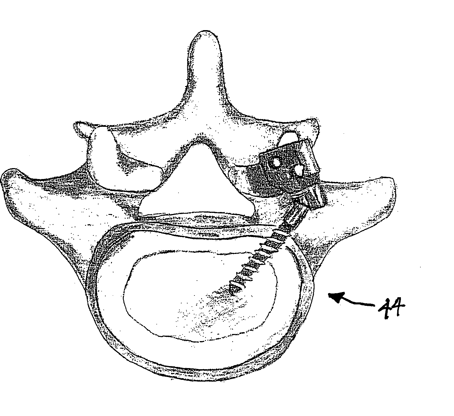
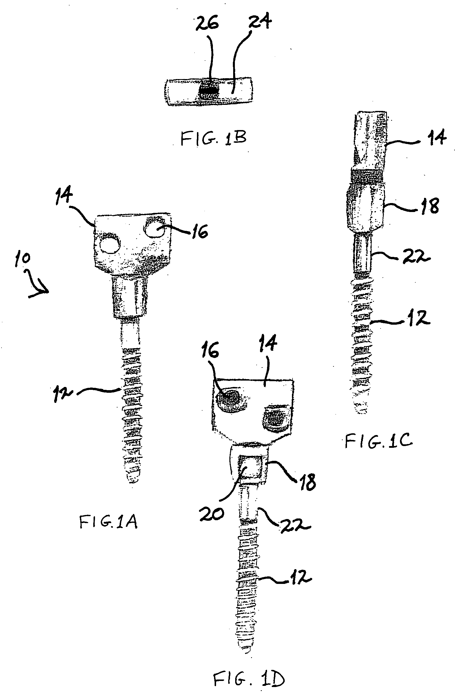
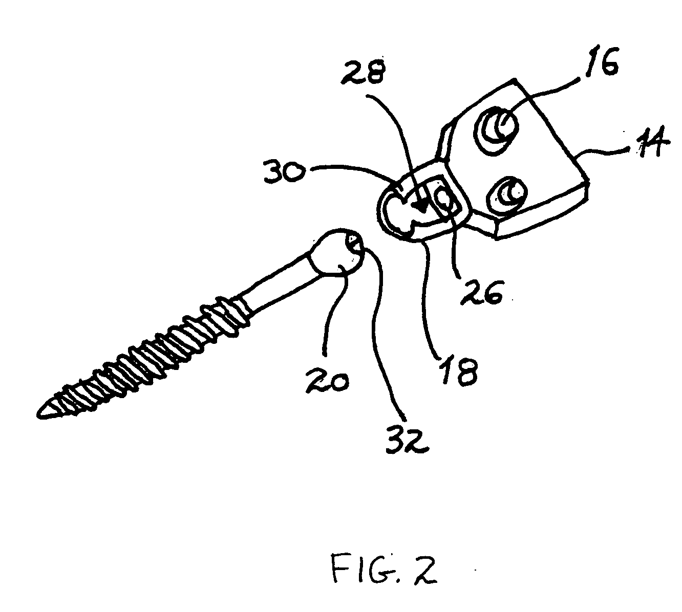
[0036] Referring now to the drawings, in which like reference numerals identify similar or identical elements throughout the several views, and in particular to FIGS. 1-3, there is shown the facet joint prosthetic device of the present invention. Preferably, prosthetic device 10 is comprised of an anchoring member 12, which is both rotatably and pivotably attached to a plate member 14. Anchoring member 12 is preferably a bone screw, having threads of sufficient pitch and thickness to allow anchoring member 12 to be self-tapping into the bone of the vertebrae to which it is to be secured. Although anchoring member is preferably a bone screw, other anchoring means for bone securement are also contemplated. Preferably, prosthetic device 10 is made of any non-absorbable, bio-compatible material of the prosthetic arts, such as titanium, stainless steel, porcelain, or a combination of these materials.

[0037] Plate member 14 is preferably provided with a pair of securing holes 16, through ...


PUM


Abstract

A prosthetic device for replacing a facet joint in the spine of a patient is provided. The prosthetic device includes an anchoring member and a plate member rotatably and pivotably connected to each other by a ball and socket mechanism. The anchoring member is preferably in the form of a bone screw for placement into the pedicle/facet intersection of a vertebrae, and the plate member is provided with securing holes for securing the plate member to an adjacent vertebrae. A minimally invasive, percutaneous surgical method is also provided for replacing the facet joint in the spine, and a kit for performing the surgical method is also provided.

Description

PRIORITY [0001] This application claims priority to a provisional application entitled “PERCUTANEOUS FACET JOINT PROSTHESIS”, filed in the U.S. Patent and Trademark Office on Feb. 18, 2004 and assigned Ser. No. 60 / 545,449, the contents of which are incorporated herein by reference.BACKGROUND [0002] 1. Field of the Invention [0003] The present invention relates generally to prosthetic devices, and in particular to a prosthetic device for replacing a facet joint in the spine of a patient, and to a method for replacing a facet joint in the patient's spine. [0004] 2. Description of the Related Art [0005] Degenerative diseases of the spine are a major cause of morbidity in the United States and around the world. Back pain is one of the leading causes of disability in this country, and costs billions of dollars each year to both patients and their insurance companies. Back pain is the most common reason for patients to consult doctors in this country. [0006] The human spine supports and s...

Claims


Application Information

Patent Timeline
Patent Type & Authority Applications(United States)
IPC IPC(8): A61B17/00A61B17/02A61B17/34A61B17/70A61B17/86A61B17/88A61F2/00A61F2/30A61F2/44
CPCA61B17/3421A61F2310/00335A61B17/7064A61B2017/00362A61F2/4405A61F2002/30378A61F2002/305A61F2002/30649A61F2002/30772A61F2002/3085A61F2220/0025A61F2220/0033A61F2310/00017A61F2310/00023A61B17/3468
Inventor BOEHM, FRANK H. JR.MELNICK, BENEDETTA DELORENZO
Owner BOEHM FR H JR
Why Eureka
Try Eureka