Materials handling and treatment

a technology of material handling and treatment, applied in the direction of filtration separation, moving filter element filter, separation process, etc., can solve the problems of difficult ensuring, messy process, uneven sludge spread across the bel

Inactive Publication Date: 2015-01-22
GRAHAM NEIL DERYCK BRAY +1
View PDF9 Cites 0 Cited by
  • Summary
  • Abstract
  • Description
  • Claims
  • Application Information

AI Technical Summary

Benefits of technology

[0016]The tube structure may be subjected to a compression as it undergoes deflection in passing around one or more of the roller structures. Further, the tube structure may undergo compression as a result of tension which is exerted on the tubular structure by virtue of axial tension on the belt portion and also tension arising from the loading exerted by material contained within the tubular structure. Such compression may assist in treatment of material contained in the tubular structure. Where the treatment involves dewatering of the material, the compression may assist in squeezing water from the material.

Problems solved by technology

Even so, in operation, the spread of the sludge is not uniform across the belt and the entire belt is generally not used.
Also there is a degree of spatter associated with the spreading of the sludge onto the belt and thus the process can be somewhat messy.
A particular problem with such belt filter presses is the difficulty in ensuring that the belts track correctly around the guide rollers, particularly at the region of the pressure zone where the belts co-operate to press the material undergoing treatment.
However, it is limited in its applications to small capacity as it sags between the holding / compaction rollers which can result in stretching of the belts if over loaded.
Further, it does not allow for a high hydrostatic pressure head as the liquid can only be filled to the top of the “V” bolt.
The presence of folds, creases or wrinkles can be problematic in relation to uniform compression of the confined material.

Method used


Image

  • Materials handling and treatment
  • Materials handling and treatment
  • Materials handling and treatment

Examples


first embodiment

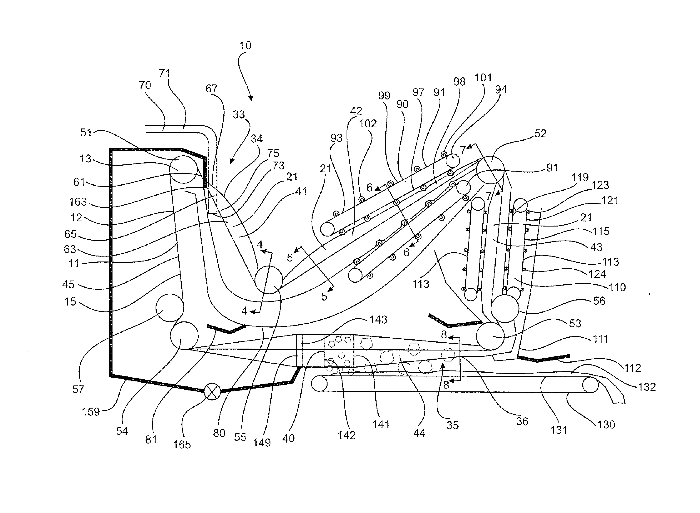
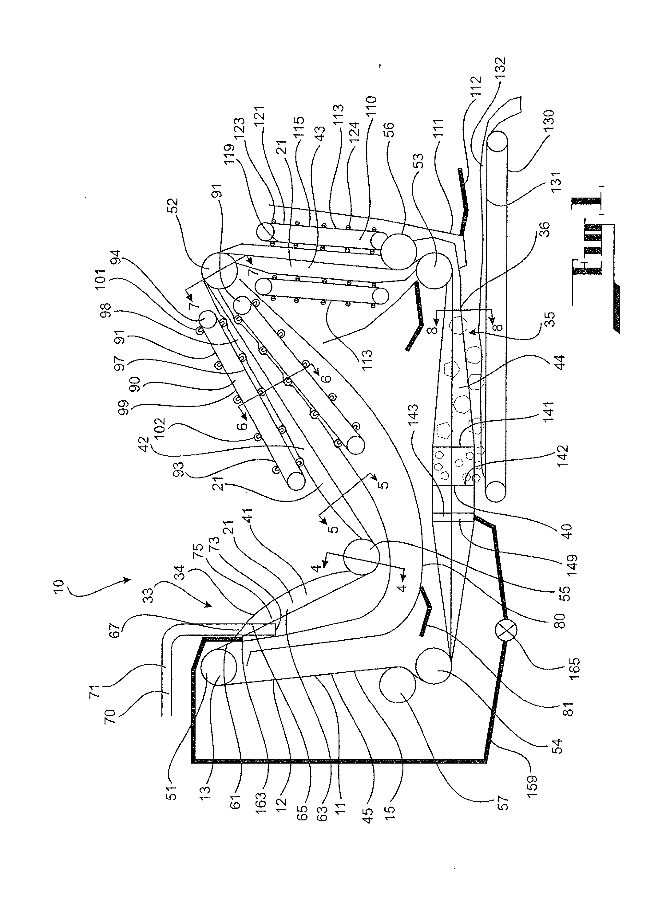
[0081]The first embodiment, which is shown in FIGS. 1 to 11 of the drawings, is directed to a belt filter apparatus 10 for treating material to separate solid and liquid components thereof. The apparatus 10 according to this embodiment has been devised particularly for treating sludge material such as sewage for the purposes of dewatering the sludge material to facilitate recovery of the solid matter for subsequent treatment. There may, of course, be various other applications for the belt filter apparatus 10.

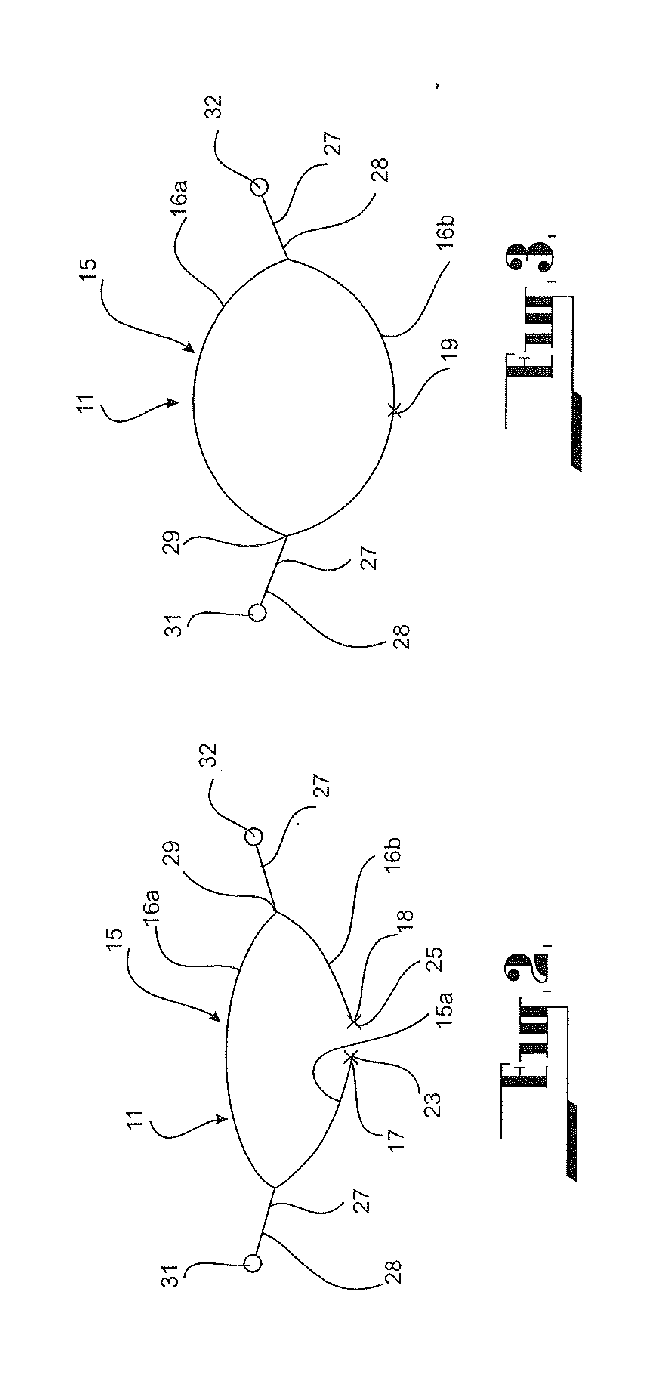
[0082]The apparatus 10 comprises an endless belt structure 11 adapted to circulate around a path 12 incorporating guide roller structures 13 around which the belt structure passes.

[0083]The endless belt structure 11 comprises an elongate belt portion 15 formed of sheet material; specifically, water permeable sheet material, such as for example a flexible filter pad material such as woven polypropylene. The belt portion 15 comprises two opposed longitudinal edges 17, 18. The bel...

second embodiment

[0130]Referring now to FIGS. 12 and 13, there is shown a belt filter apparatus 200 according to a This embodiment is similar in some respects to the previous embodiment and similar reference numerals are used to denote corresponding parts.

[0131]In this embodiment, the tubular structure 21 turns about two turn rollers 201 in moving between the first run 41 and the second run 42. The two rollers 201 are spaced apart and a section 203 of the tubular portion 21 draped therebetween.

[0132]The belt filter apparatus 200 includes two pressing stations 90, 110 as was the case with the previous embodiment. However, in this embodiment, the second pressing station 110 is arranged along a horizontal run 205 of the belt structure 11 rather than a vertical run. Further, at the pressing station 110, the cams 123 on opposed sides of the tubular structure 21 locate between each other to subject the tubular structure 21 to a peristaltic pressing action, as best seen in FIG. 13. The pressing station 11...

fourth embodiment

[0140]Referring now to FIGS. 16 to 21, there is shown a belt filter apparatus 300 for treating material to separate solid and liquid phases thereof. The apparatus 300 has been devised particularly for treating sewage for the purposes of dewatering the sewage to facilitate recovery of the solid matter for subsequent treatment. There may, of course, be various other applications for the belt filter apparatus.

[0141]The apparatus 300 comprises an endless belt structure 311 passing around guide rollers 313.

[0142]The endless belt structure 311 comprises an elongate belt portion 315 formed of water permeable material such as for example a flexible filter pad material. The belt portion 315 has two opposed longitudinal edges 317, 318. The endless belt 311 further comprises a connection means 319 for releasably connecting the two longitudinal edges 317, 318 together so as to form a tubular structure 321 having a flexible side wall 322. The connection means 319 comprises a slider connector me...


PUM

PropertyMeasurementUnit
tensionaaaaaaaaaa
axial tensionaaaaaaaaaa
gravityaaaaaaaaaa

Abstract

A belt filter apparatus for treating material to separate solid and liquid components comprises an endless belt structure adapted to circulate around a path incorporating guide roller structures around which the belt structure passes. The endless belt structure comprises an elongate belt portion of water permeable material, and has two opposed longitudinal edges. A zipper releasably connects the two longitudinal edges together to form a tubular structure with a flexible sidewall. The circulating path includes an assembly zone where the longitudinal edges are brought together and connected by the zipper to form the tubular structure, and a disassembly zone at which the zipper is released to separate the longitudinal edges and open the tubular structure. Means are provided for compressing a portion of the tubular structure to express liquid from the material contained in the tubular structure. The liquid discharges from the tubular structure through the water permeable belt portion.

Description

CROSS REFERENCE TO RELATED APPLICATIONS[0001]This application is a continuation of and claims the benefit under 35 U.S.C. §120 to U.S. application Ser. No. 14 / 149,155 by the inventors, filed Jan. 7, 2014 and pending, which in turn claims priority to U.S. application Ser. No. 12 / 304,811 by the inventors, filed May 19, 2009, now abandoned; the entire contents of each application are hereby incorporated herein.BACKGROUND[0002]1. Field of the Invention[0003]Example embodiments in general related to an apparatus for performing an operation on a material, and also to a method of treating a material using the apparatus.[0004]2. Description of Related Art[0005]It is known to use belt filter presses for separating liquids from solid suspensions. Such filters can be employed in the treatment of sewage for dewatering purposes. Typically, a belt filter comprises two tensioned endless belts circulating around guide rollers with a pressure zone defined between the two belts. In addition to the pr...

Claims


Application Information

Patent Timeline
Patent Type & Authority Applications(United States)
IPC IPC(8): B01D33/056B01D33/44B01D33/048
CPCB01D33/0565B01D2033/052B01D33/44B01D33/048B01D33/646B01D33/642B01D33/042B65G15/08B30B9/245B65G15/40B01D33/052
Inventor GRAHAM, NEIL DERYCK BRAYGRAHAM, ARTHUR DERRICK BRAY
Owner GRAHAM NEIL DERYCK BRAY
Why Eureka
Try Eureka