
Image formation apparatus

Active Publication Date: 2015-01-22
KONICA MINOLTA INC
View PDF2 Cites 0 Cited by
  • Summary
  • Abstract
  • Description
  • Claims
  • Application Information

AI Technical Summary

Benefits of technology

This patent is about an image formation apparatus that can create toner images on a photosensitive body. The apparatus includes a coverage calculation unit that calculates the surface area of the toner deposition region in a target page, a prediction unit that predicts if image noise will occur in the next page based on the coverage value, and a sheet interval control unit that adjusts the rotation distance of the photosensitive body based on the prediction. The technical effect of this patent is to improve the image quality and prevent image noise in a color image formation apparatus.

Problems solved by technology

As a consequence, an electrostatic latent image which is not related to image data is formed on the photosensitive body and when the electrostatic latent image is developed, image noise (i.e., a so called ghost image) occurs on a recording sheet which is undergoing a printing process.
Unfortunately, in the art described above, an operation of removing residual charge from the photosensitive body by applying electrical charge is performed while printing jobs are suspended.
Therefore, the art described above suffers from a problem of being unable to prevent image noise, occurring due to accumulation of residual charge in the photosensitive body, during performance of an image formation operation.
Unfortunately, in order to perform the removal operation during the aforementioned period, the period is required to be long enough for the photosensitive body to rotate once, resulting in a problem of reduced image formation productivity.

Method used


Image

  • Image formation apparatus
  • Image formation apparatus
  • Image formation apparatus

Examples


modified examples

[0112]The present invention is explained based on the above embodiment, but the present invention is of course not limited to the embodiment. For example, the present invention may alternatively be implemented as explained in any of the following modified examples.

[0113](1) In the embodiment, the image noise prediction table used during image noise prediction processing is the default prediction table, and thus only coverage is taken into account when predicting whether or not image noise will occur. Alternatively, humidity, usage amount of the photosensitive drums, or both humidity and usage amount may also be taken into account during image noise prediction processing.

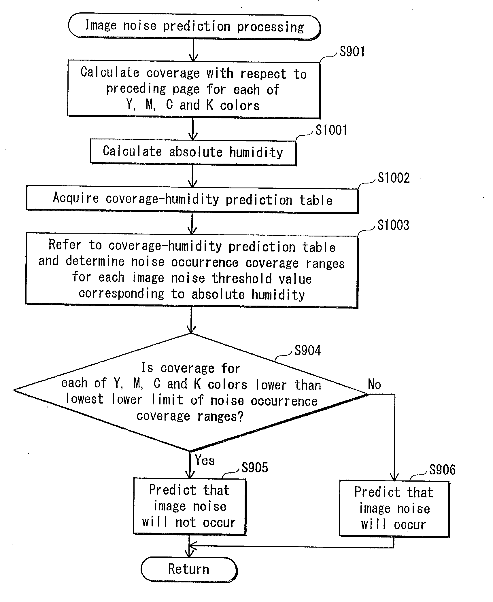
[0114]For example, the image noise prediction table stored in the image noise prediction table storage unit 611 may alternatively be a coverage-humidity prediction table, and image noise prediction processing illustrated in FIG. 9 may be modified as illustrated in FIG. 10. For example, the image noise prediction tabl...


PUM


Abstract

An image formation apparatus applies electrical charge to an image carrier surface of a photosensitive body during a period between light exposure scanning for successive pages, and performs a first control such that rotation distance of the photosensitive body during the period is shorter than circumferential length thereof. The image formation apparatus includes a coverage calculation unit that calculates coverage of a target page, a prediction unit that, when inter-image distance between images of the target page and a next page, in terms of a sub-scanning direction, is shorter than the circumferential length, predicts whether image noise will occur for the next page based on the coverage, and a sheet interval control unit that, upon the prediction unit predicting affirmatively, suspends the first control and performs a second control on the rotation distance such that the inter-image distance is extended to be at least as long as the circumferential length.

Description

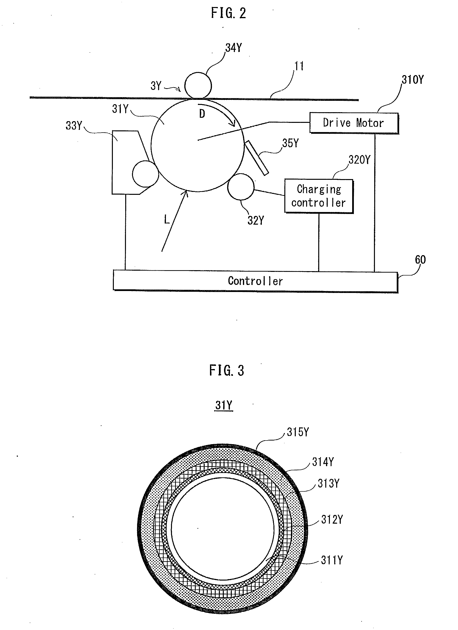
CROSS-REFERENCE TO RELATED APPLICATION[0001]This application is based on an application No. 2013-148394 filed in Japan, the contents of which are hereby incorporated by reference.BACKGROUND OF THE INVENTION[0002](1) Field of the Invention[0003]The present invention relates to an image formation apparatus such as a printer or a photocopier, and in particular relates to an art of, during an image formation operation, removing residual electrical charge accumulated in a photosensitive body.[0004](2) Description of the Related Art[0005]In terms of image formation apparatuses using an electrophotographic process, in recent years it has become common to use an image formation apparatus which includes a photosensitive body having a protective layer formed at an outer most surface thereof in order to improve durability of the photosensitive body.[0006]FIG. 16 is a cross-sectional diagram schematically illustrating one example of layer configuration of the aforementioned photosensitive body....

Claims


Application Information

Patent Timeline
IPC IPC(8): G03G15/00G03G21/00
CPCG03G15/50G03G21/20G03G15/5025
Inventor ISHIDA, HIROFUMI
Owner KONICA MINOLTA INC
Learn More