Method for driving lumiscent display panel by Prime Reset organic electroluminecence

A technology of luminous display and driving method, applied in static indicators, instruments, etc., can solve problems such as power consumption, achieve the effect of good depth, reduce power consumption, and eliminate residual charge

Inactive Publication Date: 2003-10-29
李吉在
View PDF0 Cites 0 Cited by
  • Summary
  • Abstract
  • Description
  • Claims
  • Application Information

AI Technical Summary

Problems solved by technology

Moreover, the data input time of the data line provided at this time is also consistent, and there may be some problems in timing
In the

Method used


Image

  • Method for driving lumiscent display panel by Prime Reset organic electroluminecence
  • Method for driving lumiscent display panel by Prime Reset organic electroluminecence
  • Method for driving lumiscent display panel by Prime Reset organic electroluminecence

Examples


Example Embodiment

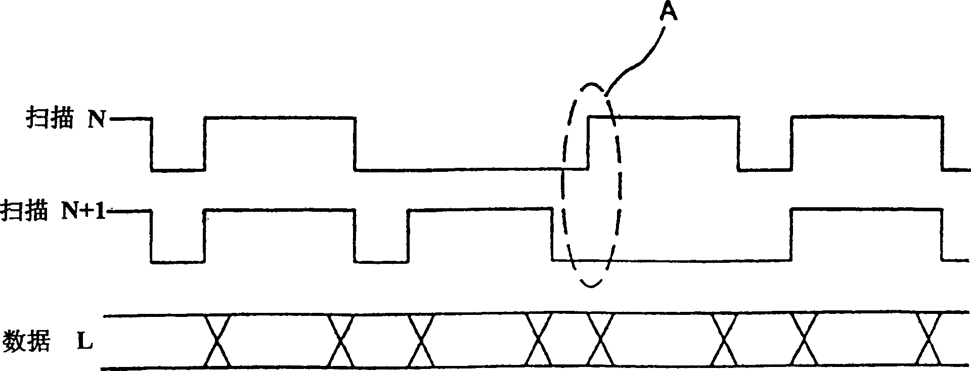
[0022] Such as Figure 4 As shown, in the scanning line of the present invention, the ground potential is applied to the selected line based on the positive potential and light is emitted, and finally reset.

[0023] Such as Figure 4 As shown in part B of the scan line, when the selected part of the scan line is over, select scan N+1 to reduce power consumption. Taking into account the relationship with the scanning line, the potential applied to the data line is not higher than the potential of the scanning line, a clockwise bias is applied to the selected line, and the light-emitting brightness is adjusted according to the amount of current passed at this time. And at other times when there is no light, the ground voltage shall prevail.

[0024] After the progressive scan is over, if one Prime is displayed, a sufficiently long initialization interval is inserted between Prime and Prime to eliminate the remaining charge of the entire pixel. In addition, at this time, the same po...


PUM


Abstract

A drive method using Prime Reset for organic electroluminescent display board is disclosed. It can decrease the electric consumption and minimize the variation of scan waveform. For the line chosen from multiple scan lines, the voltage provided for it can only shift only when it emits light and the voltage is supplied to data line in its luminescent area.

Description

technical field [0001] The invention relates to a driving method of an organic electroluminescent display panel using Prime Reset, which reduces power consumption of the organic electroluminescent display panel and minimizes changes in scanning waveforms; ensures the stability of the display panel potential and uses Reset waveform. The invention relates to a driving method capable of driving an organic light-emitting display panel by adopting a new driving waveform. Background technique [0002] Generally, an organic electroluminescent light emitting display device is divided into data lines and scan lines. The data line is made of ITO, and the electrodes are installed in one direction; the scanning line is made of metal, and has a matrix structure that can be installed in one direction or two directions. [0003] figure 1 It is an ordinary organic electroluminescent light-emitting display element. Such as figure 1 As shown, it has a matrix structure. Due to a certain ...

Claims


Application Information

Patent Timeline
IPC IPC(8): G09G3/30
Inventor 李吉在
Owner 李吉在
Why Eureka
Try Eureka