Gas turbine arrangement alleviating stresses at turbine discs and corresponding gas turbine

Inactive Publication Date: 2015-01-22
SIEMENS AG
View PDF7 Cites 2 Cited by
  • Summary
  • Abstract
  • Description
  • Claims
  • Application Information

AI Technical Summary

Benefits of technology

[0013]It is an object of the invention to provide an alternative or improved design reducing stress concentration in the disc at the bottom of a disc slot

Problems solved by technology

Rotating part may b

Method used


Image

  • Gas turbine arrangement alleviating stresses at turbine discs and corresponding gas turbine
  • Gas turbine arrangement alleviating stresses at turbine discs and corresponding gas turbine
  • Gas turbine arrangement alleviating stresses at turbine discs and corresponding gas turbine

Examples


Example

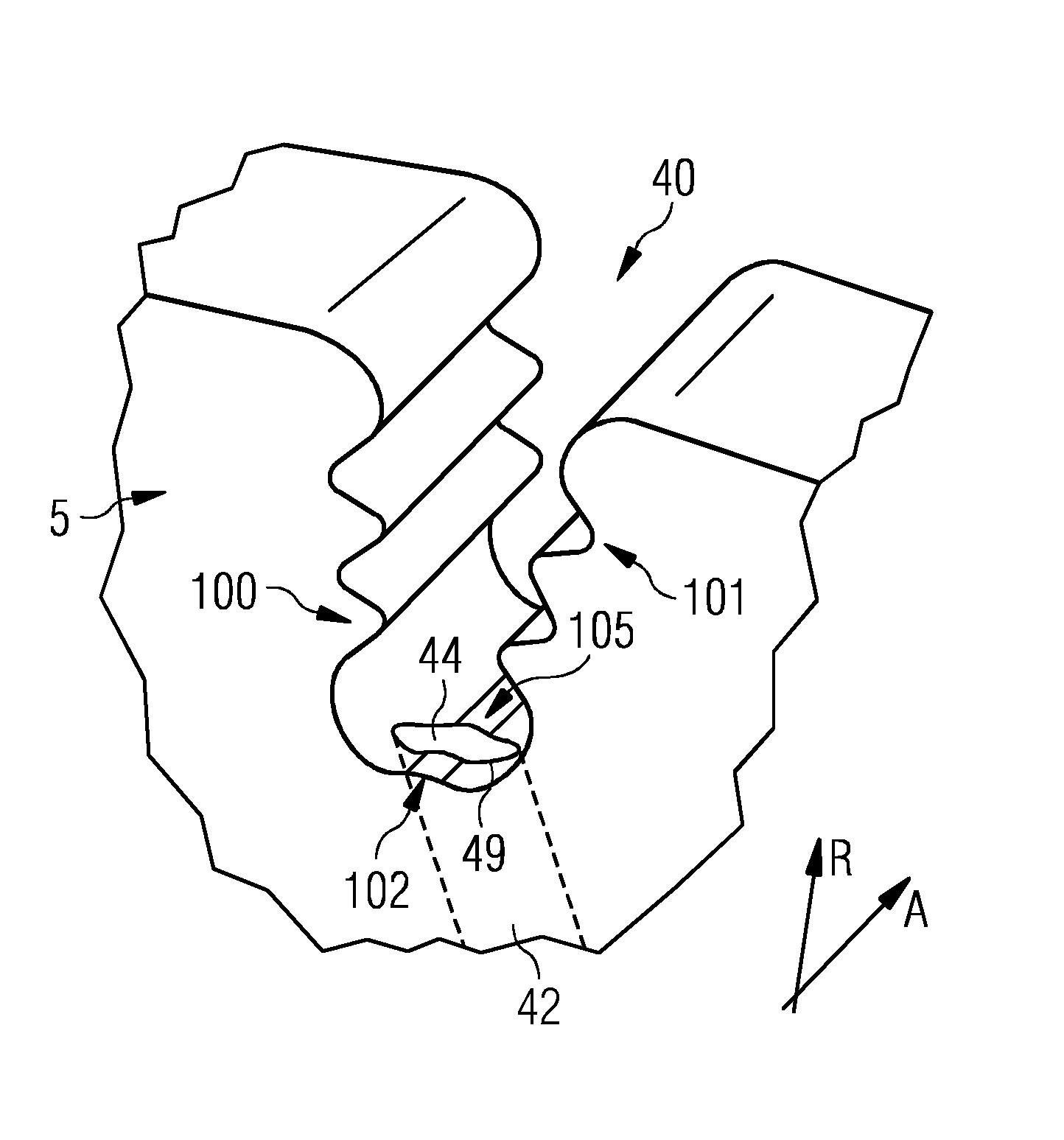
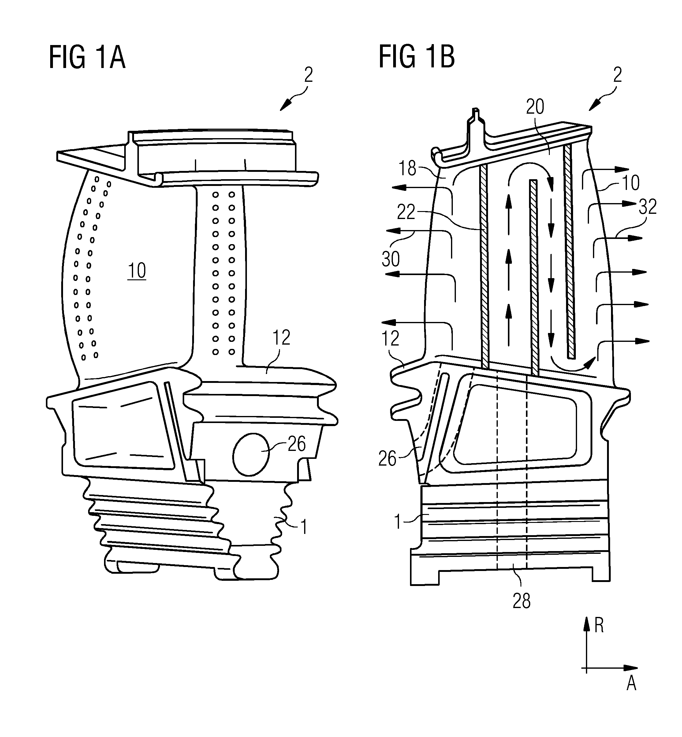
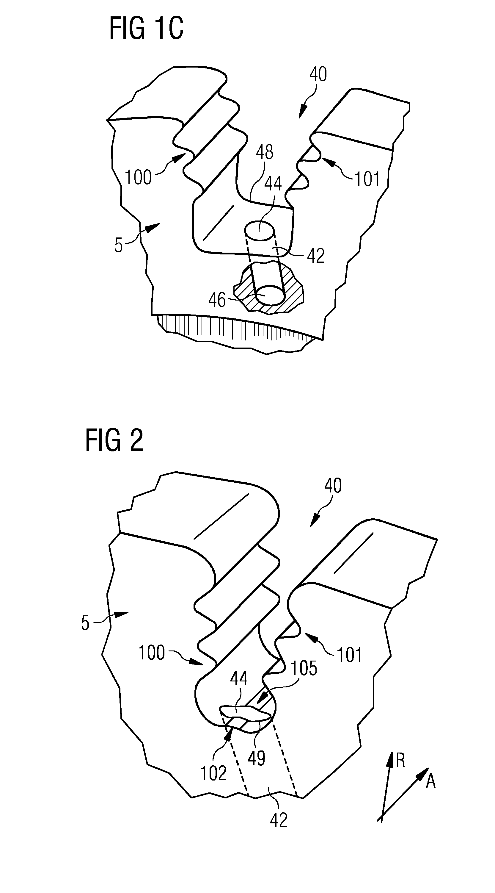
[0047]FIGS. 1A and 1B show a blade design that is known from the prior art and that will slightly be modified according to aspects of the invention, which is then later shown in FIG. 3. FIG. 1C shows a prior art rotor disc design, which is updated according to aspects of the invention as shown in FIGS. 2 and 3.

[0048]FIG. 1A shows a rotor blade 2 of a gas turbine engine in a perspective view. FIG. 1B shows the same rotor blade 2 in a cross sectional view, the cross section being located in a plane defined by an axial direction A—parallel to an axis of rotation of the engine—and a radial direction R—perpendicular to the axis of rotation. The rotor blade 2 is made up of an aerofoil section 10, a platform 12, and a blade root portion 1. The blade root portion 1 engages with a correspondingly shaped slot in a rotor disc. The blade root portion 1 is configured as “fir tree” shape, this being often preferred because of its excellent resistance against the centrifugal forces exerted upon th...


PUM


Abstract

A turbine arrangement is provided, particularly a gas turbine arrangement, having at least one rotor blade and a turbine disc, the rotor blade having a root portion, the turbine disc having at least one slot in which the root portion of the rotor blade is secured. The slot has a plurality of opposite pairs of slot lobes and a plurality of opposite pairs of slot fillets, and a slot bottom of the slot. The slot bottom is arranged to have a first convex surface section. Furthermore the root portion of the rotor blade has a root bottom with a first concave surface section corresponding to the first convex surface section of the slot bottom. Additionally, the first convex surface section is pierced by an outlet of a cooling duct through the turbine disc.

Description

CROSS REFERENCE TO RELATED APPLICATIONS[0001]This application is the US National Stage of International Application No. PCT / EP2012 / 073354 filed Nov. 22, 2012, and claims the benefit thereof. The International Application claims the benefit of European Application No. EP12159202 filed Mar. 13, 2012. All of the applications are incorporated by reference herein in their entirety.FIELD OF THE INVENTION[0002]The present invention relates generally to a turbomachine assembly, particularly an assembly of a rotor blade and a rotating turbine disc, preferably in a hot turbine section of a gas turbine engine.BACKGROUND OF THE INVENTION[0003]A turbine section of a gas turbine typically has a plurality of rows of stationary vanes and rotary blades. The blades of one row are usually identical to each other and include an aerofoil portion, a platform portion, and a root portion. Some blade rows may additionally include a shroud portion preventing the hot gases escaping over the blade tip. In refe...

Claims


Application Information

Patent Timeline
IPC IPC(8): F01D5/18F01D5/30
CPCF01D5/3007F01D5/18F05D2250/711F01D5/081F05D2250/712
Inventor BLUCK, RICHARDHUGHES, MARTIN
Owner SIEMENS AG
Why Eureka
Try Eureka