Method of coding a holographic pattern, a corresponding coding device and computer program

a holographic pattern and coding technology, applied in the field of image processing, can solve the problems of poor localization of information in holographic patterns and poor adaptability to conventional coding techniques, and achieve the effects of reducing the time and complexity required, reducing the cost of signaling, and optimizing the cost of coding significantly

Active Publication Date: 2015-01-29
ORANGE SA (FR)
View PDF6 Cites 1 Cited by
  • Summary
  • Abstract
  • Description
  • Claims
  • Application Information

AI Technical Summary

Benefits of technology

[0016]By means of reconstructing the light signal in this way in the form of a plurality of rays in the space domain, instead of reconstructing said signal by applying an inverse Fresnel transform, it becomes possible to reduce in non-negligible manner the time and the complexity required for performing the calculations for coding a holographic pattern.
[0017]In addition, such reconstruction coupled to making use of rays in the form of a plurality of views respectively representing a plurality of perspectives of the same 3D scene thus makes it possible to take advantage in optimum manner of the multiple redundancies that exist in space and time between the different views in order to code the holographic pattern effectively.
[0021]Such transforms have the advantage of effectively localizing the spatial frequencies associated with a given position in the hologram.
[0023]Such a provision has the advantage of associating clusters of pixels with the intensity value of a reference pixel.
[0025]Such a provision also has the advantage of allocating to pixel clusters the intensity value of a reference pixel.
[0031]Such a provision makes it possible during coding to optimize the elimination of space and time redundancies between the N views of the resulting multi-view image in order significantly to reduce the cost of coding.

Problems solved by technology

Information in a holographic pattern is thus very poorly localized, and therefore lends itself poorly to conventional coding techniques.

Method used


Image

  • Method of coding a holographic pattern, a corresponding coding device and computer program
  • Method of coding a holographic pattern, a corresponding coding device and computer program
  • Method of coding a holographic pattern, a corresponding coding device and computer program

Examples


Embodiment Construction

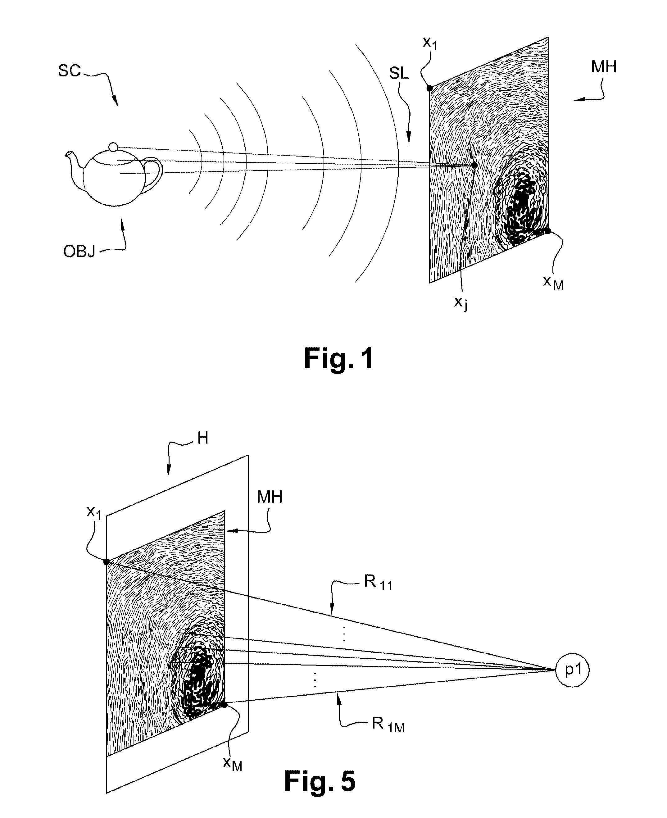
[0056]There follows a description of an implementation in which the coding method of the invention is used to code a current holographic pattern MH as shown in FIG. 1, having recorded therein a light signal SL representative of light received by at least one perspective object OBJ in a three-dimensional scene SC. In the example shown, the object OBJ is a teapot. In a method that is itself known, the holographic pattern MH contains a plurality of points x1, x2, . . . , xj, . . . , xM, with 1≦j≦M, which points are obtained by discretizing at a determined sampling pitch.

[0057]The holographic pattern MH may be single or it may form part of a set of patterns representing the same object and indexed in time, in other words a frame of a holographic video.

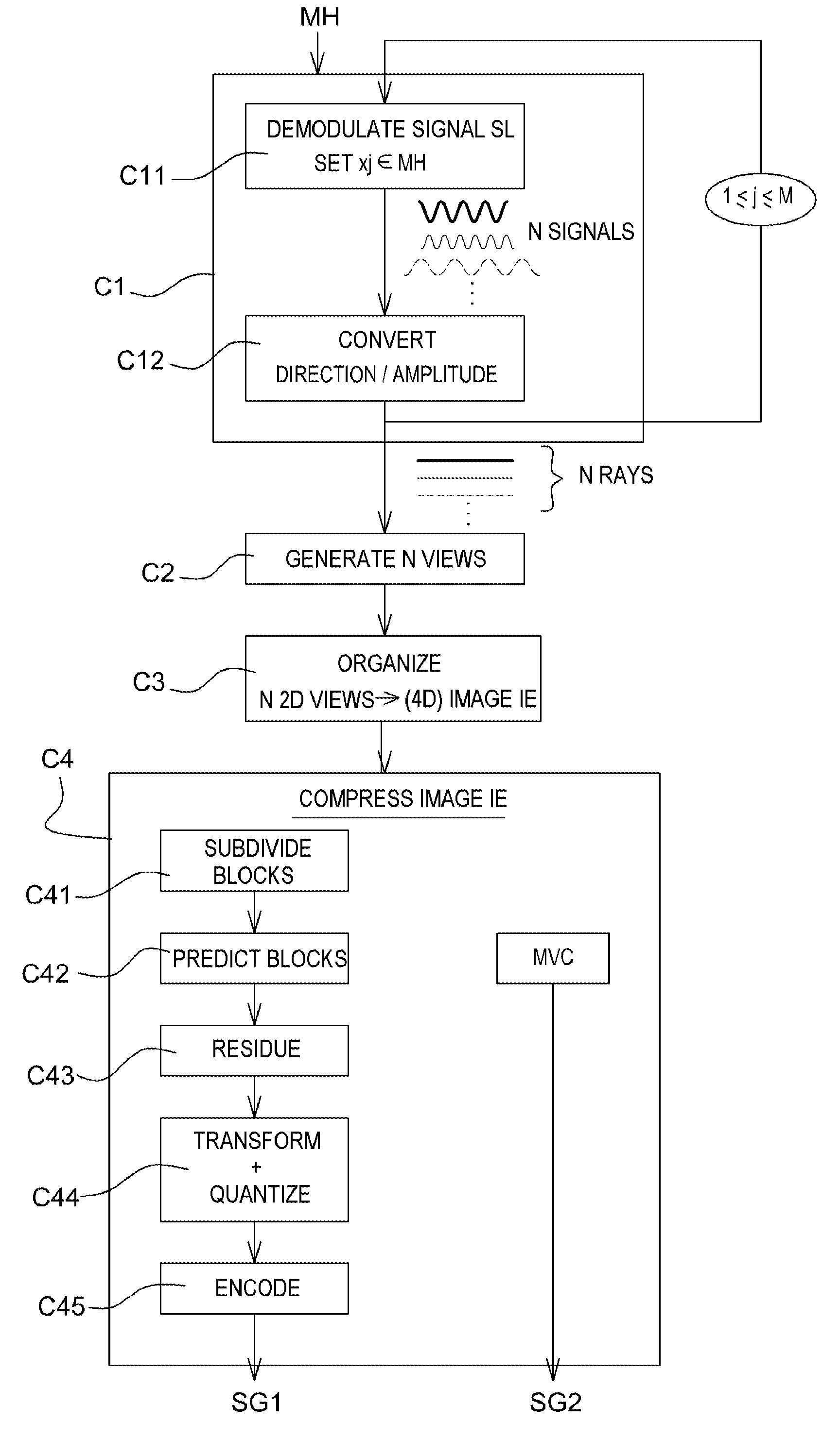
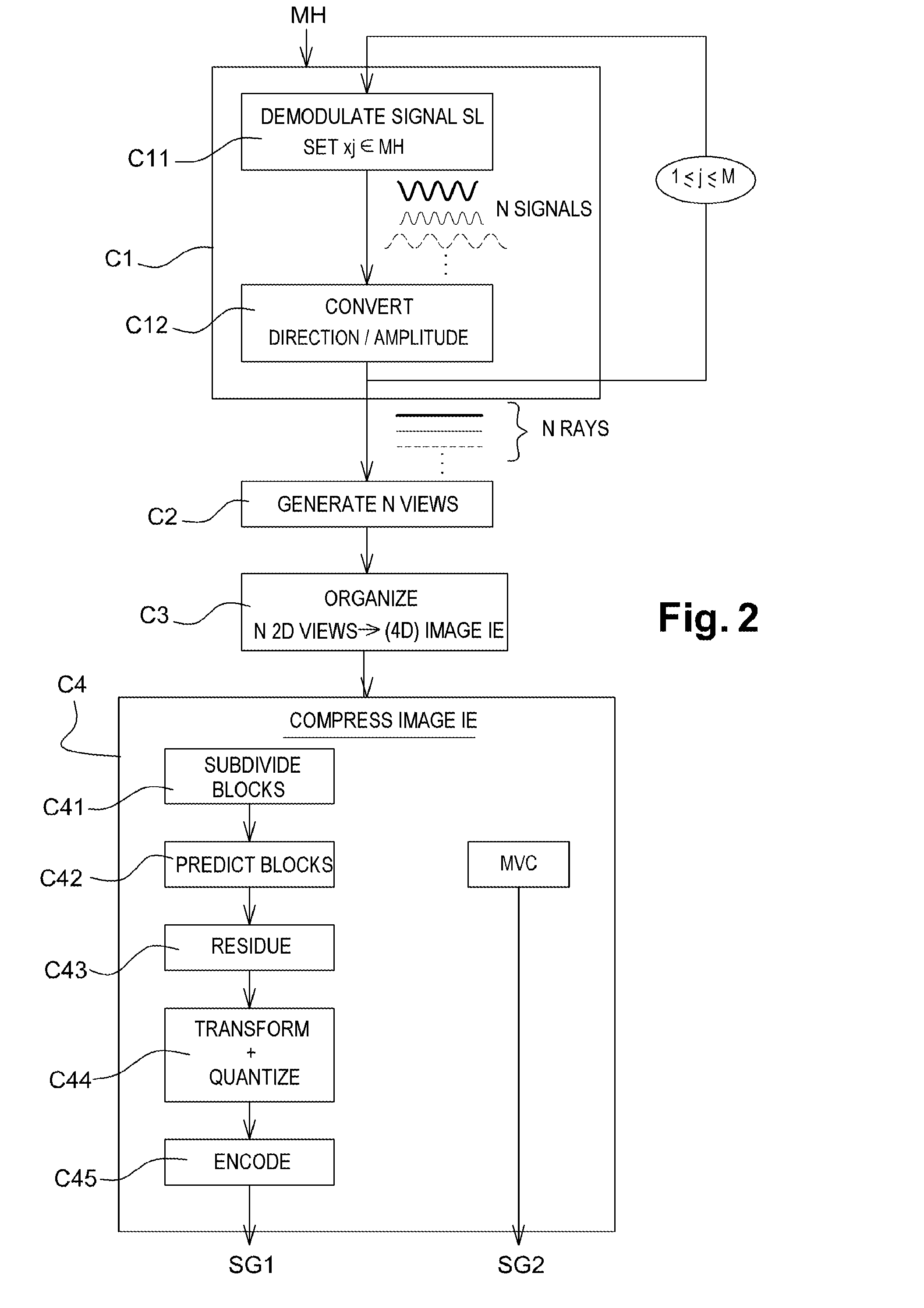
[0058]FIG. 2 shows the coding method of the invention in the form of an algorithm comprising steps C1 to C4.

[0059]In the implementation of the invention, the coding method of the invention is performed in a coder device C0 shown in FIG. 3....


PUM


Abstract

A method for coding at least one holographic pattern recording a light signal representative of light received by a perspective object in a scene. The method includes: determining, from the light signal and for each point xj(1≦j≦M) of the holographic pattern, a set of N light rays passing through the point and corresponding respectively to N different viewing positions for viewing the pattern; generating from the M sets of N determined light rays, a plurality N of two-dimensional views of the object corresponding respectively to the N viewing positions of the pattern, by causing M determined rays to intersect at each of the viewing positions that are contained in a viewing plane parallel to a plane containing the holographic pattern; arranging the N generated views as a multi-view image of the object, the N views corresponding respectively to sub-images of the multi-view image; and compressing the multi-view image.

Description

CROSS-REFERENCE TO RELATED APPLICATIONS[0001]This Application is a Section 371 National Stage Application of International Application No. PCT / FR2013 / 050284, filed Feb. 12, 2013, the content of which is incorporated herein by reference in its entirety, and published as WO 2013 / 121140 on Aug. 22, 2013, not in English.FIELD OF THE INVENTION[0002]The present invention relates in general to the field of image processing, and more precisely to coding three-dimensional (3D) images and sequences of three-dimensional images.[0003]More particularly, the present invention relates to coding at least one holographic pattern storing a light signal representative of the light received by at least one perspective object in a scene.[0004]The invention may apply particularly, but not exclusively, to video coding performed using current video coding schemes and amendments thereto (MPEG, H.264, H.264 SVC, H.264 MVC, etc.) or future amendments (ITU-T / VCEG (H.265) or ISO / MPEG (HEVC)), and to the corresp...

Claims


Application Information

Patent Timeline
Patent Type & Authority Applications(United States)
IPC IPC(8): G03H1/08
CPCG03H1/0841G03H1/22G03H2001/2242G03H1/0808
Inventor GIOIA, PATRICK
Owner ORANGE SA (FR)
Why Eureka
Try Eureka