Light Guide

Active Publication Date: 2015-01-29
LEE IN OK
View PDF15 Cites 7 Cited by
  • Summary
  • Abstract
  • Description
  • Claims
  • Application Information

AI Technical Summary

Benefits of technology

The present invention relates to a light guide that improves the distribution of light emitted from a light source. The lower part of the light guide has a conical surface and a bottom face, which increases the light-receiving probability and improves brightness distribution. The conical surface also reduces the illuminating angle of the light, reducing the impact of the conical angle on the light output directions. Additionally, the conical surface is connected to the deflecting portion of the light guide, allowing for smaller lights to be transmitted and reducing light leakage. Overall, the technical effects of this invention are improved brightness distribution and reduced light leakage.

Problems solved by technology

However, although the secondary reflection can effectively reduce the non-uniform luminance distribution of the light emitting portion 93, the light ray might not be able to return to the interior of the body 94 after transmitting the deflecting portion 94, such that the light ray could directly be emitted to outside of the body 9, causing light leakage at the deflecting portion 94.

Method used


Image

  • Light Guide
  • Light Guide
  • Light Guide

Examples


first embodiment

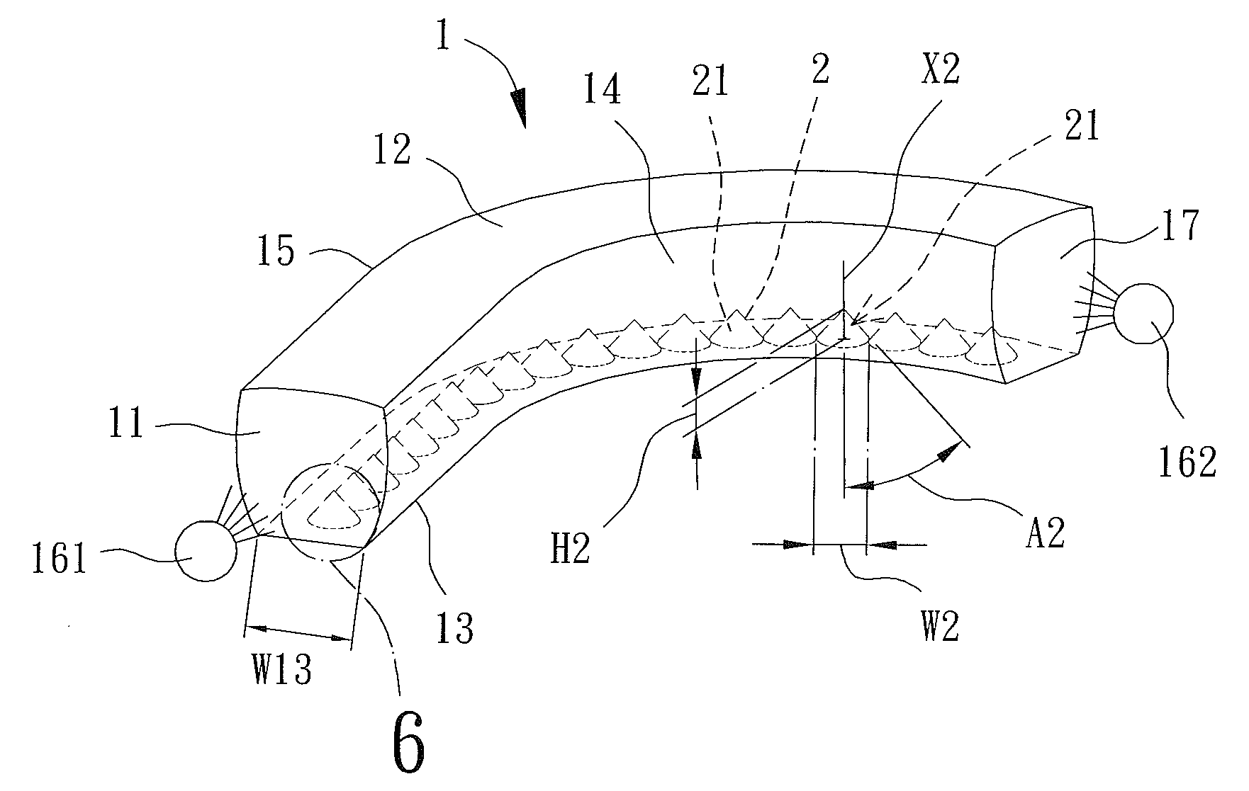
[0073]FIG. 5 is a schematic, perspective view of a light guide of a first embodiment according to the present invention. The light guide includes a body 1 transmittable to light and a plurality of light guiding elements 2. The light guiding elements 2 are arranged in the body 1. The body 1 includes a first end face 11 on an end thereof. The body 1 further includes a light emitting portion 12, a deflecting portion 13, and two lateral sides 14 and 15 connected to the light emitting portion 12 and the deflecting portion 13. The light emitting portion 12 and the deflecting portion 13 can be opposite to each other. The two lateral sides 14 and 15 can be connected to two sides of the deflecting portion 13, such that the body 1 forms a sealed tube. The body 1 can be made of a plastic material or other light-transmittable material, such that the body 1 forms a light-transmittable transparent tube. Furthermore, each of the light emitting portion 12, the deflecting portion 13, and the two lat...

fifth embodiment

[0099]FIGS. 18 and 19 show a light guide of a fifth embodiment according to the present invention. The fifth embodiment is different from the first, second, third, and fourth embodiments by that each light guiding element 2′ of the fifth embodiment includes a light guiding face 21′. The light guiding face 21′ is coupled to the deflecting portion 13 and has an apex 211. Nevertheless, the light guiding face 21′ is comprised of a plurality of connecting faces 212. Specifically, each connecting face 212 includes a bottom side 212a and two sides 212b. The bottom side 212a has two ends respectively connected to the two sides 212b. An end of each side 212b distant to the bottom side 212a is connected to the apex 211. The bottom side 212a is a line passing through two points on an arc C. Two bottom sides 212a respectively of two adjacent connecting faces 212 are connected to each other. Thus, any two adjacent connecting faces 212 can be connected by the side 212b to form the light guiding f...


PUM


Abstract

A light guide includes a body transmittable to light and a plurality of light guiding elements. The body includes a first end face on an end thereof. The body further includes a light emitting portion, a deflecting portion, and two lateral sides. The light emitting portion and the deflecting portion are opposite to each other. Each of the two lateral sides is connected to the light emitting portion and the deflecting portion. The first end face is connected to the deflecting portion and each of the two lateral sides. Each light guiding element includes a curved face. The curved face is a conical surface or a part of the conical surface. The curved face is coupled to the deflecting portion. The light guiding elements can be arranged on the deflecting portion in one or more rows to control the light output directions and to reduce the illuminating angle.

Description

BACKGROUND OF THE INVENTION[0001]1. Field of the Invention[0002]The present invention relates to a light guide and, more particularly, to a light guide for deflecting light rays from a light source to specific directions to control the light output angle.[0003]2. Description of the Related Art[0004]In recent years, small-size high-luminance power sources, such as light-emitting diodes (LEDs), have been widely used in various lighting devices. Although these lighting devices provide higher luminance, suitable light guides are still required to meet different light output patterns of various products by converting the light rays generated by the light sources into the desired light output patterns of the products. The light guides are used to deflect the light rays generated by the light sources to specific directions to thereby reduce the illuminating angle.[0005]FIG. 1 shows a schematic view of a conventional light guide including a light-transmittable body 9. The body 9 includes a ...

Claims


Application Information

Patent Timeline
IPC IPC(8): F21V8/00
CPCG02B6/0096G02B6/0018G02B6/001G02B6/0036
Inventor LEE, CHENG-TAO
Owner LEE IN OK
Why Eureka
Try Eureka