
Working apparatus for a limited area

a technology for working equipment and limited area, applied in the direction of carpet cleaners, distance measurement, instruments, etc., can solve the problems of time-consuming, too long, and too complex

Active Publication Date: 2015-01-29
BERNINI FAB
View PDF4 Cites 9 Cited by
  • Summary
  • Abstract
  • Description
  • Claims
  • Application Information

AI Technical Summary

Benefits of technology

This patent describes a working apparatus that has the following benefits: it saves time and energy for a robot to return to its base station, and it improves the reliability of the process of returning to the basin.

Problems solved by technology

The Applicant has observed that said electronic navigational control system for lawn-mowing robots has the following disadvantages:it is too complex, because it requires the use of two current conductor loops;the time it takes the lawn-mowing robot to return to the recharging station 3 is too long;the lawn-mowing robot can reach the base only by following a preferential direction, in particular by following the direction in which the magnetic field is zero (see line 55 in FIG. 12);it is too expensive.

Method used


Image

  • Working apparatus for a limited area
  • Working apparatus for a limited area
  • Working apparatus for a limited area

Examples


Embodiment Construction

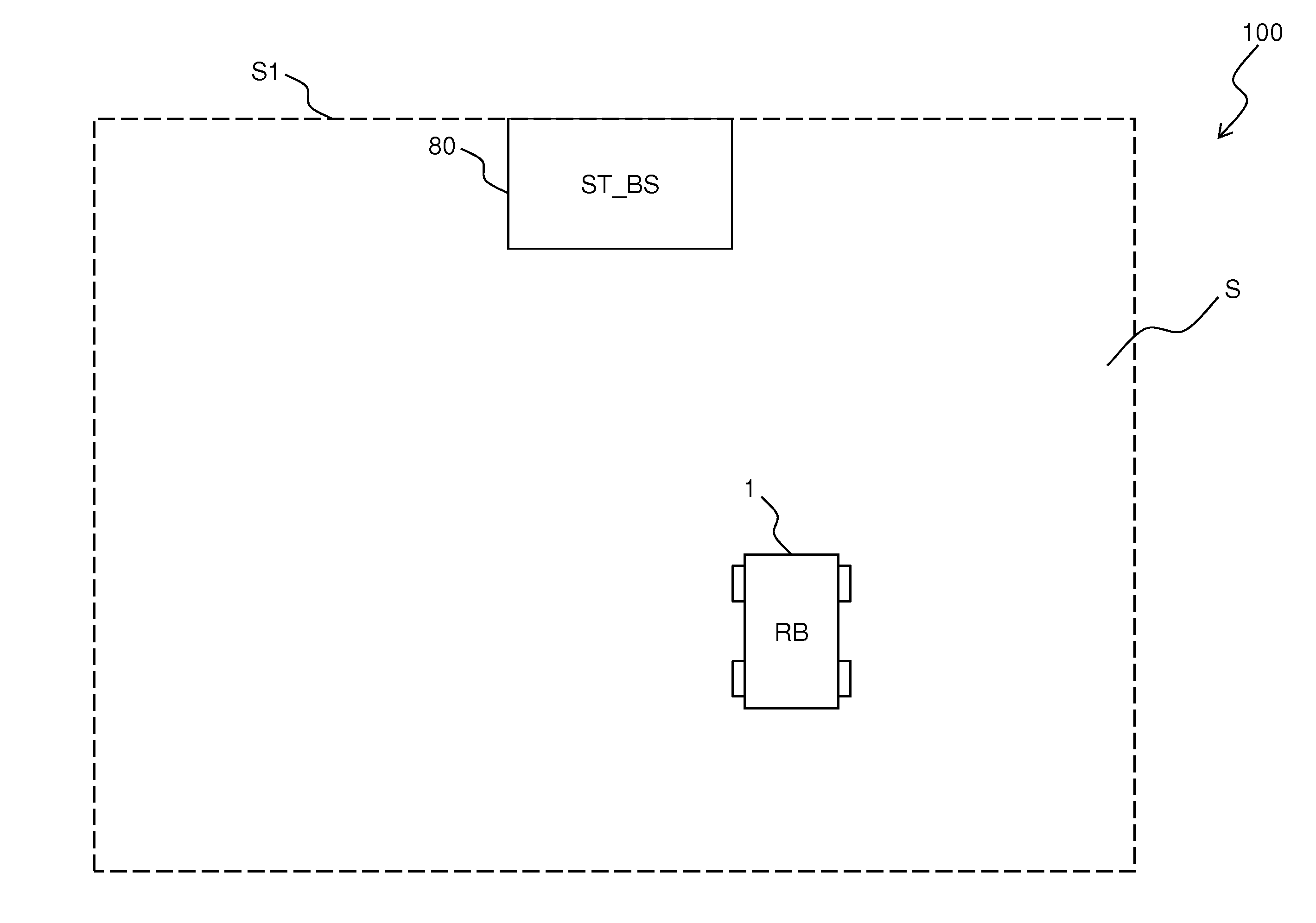
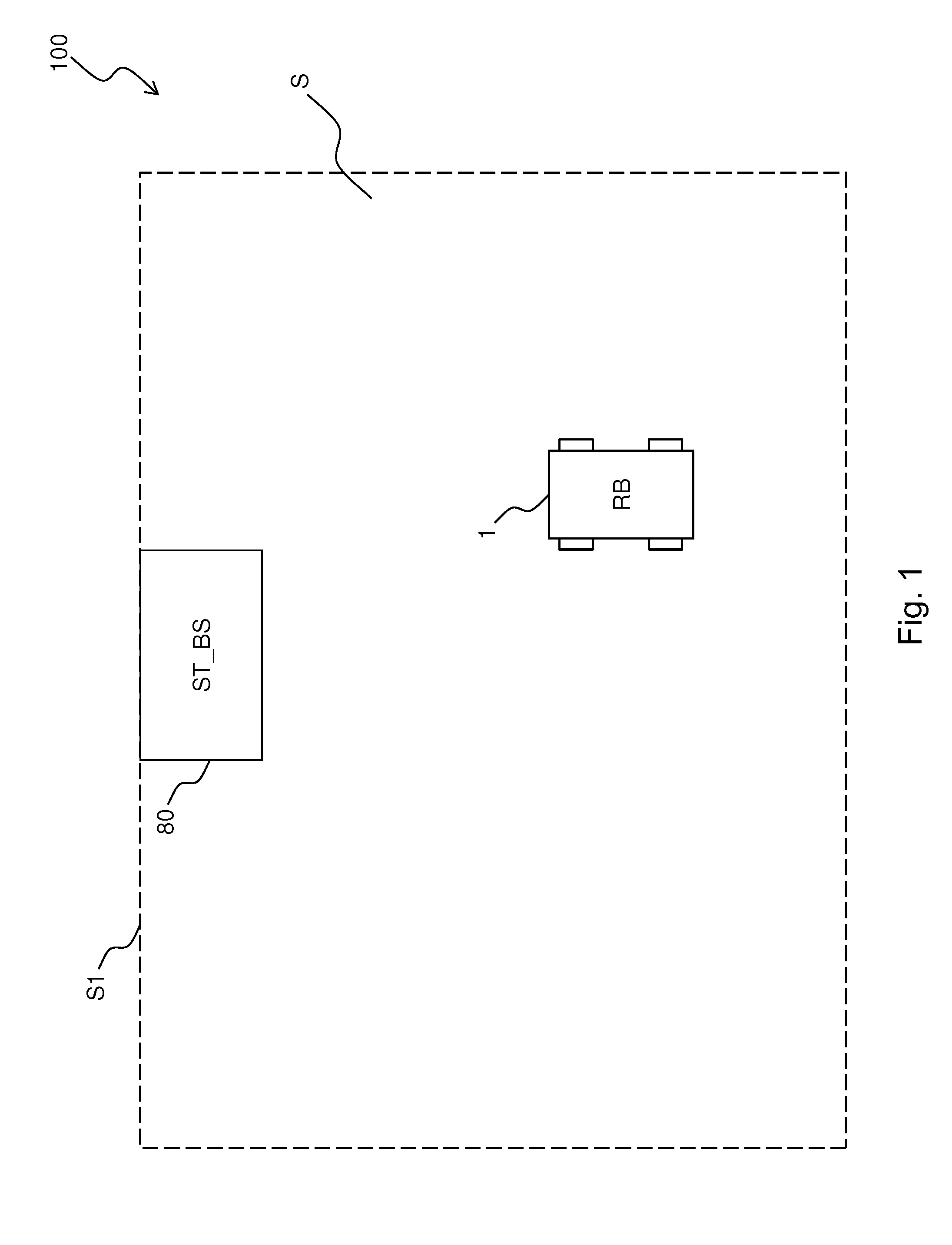
[0030]With reference to FIG. 1, it shows a working apparatus 100 for a limited area S according to one embodiment of the disclosure.

[0031]The working apparatus 100 comprises a base station 80 and a self-propelling robot 1.

[0032]The self-propelling robot 1 is configured to have a normal operating mode, a base return mode and a stand-by mode.

[0033]In the normal operating mode the self-propelling robot 1 is configured to perform a working cycle in the area S, indicated in FIG. 1 with a broken line. The self-propelling robot 1 is for example a lawn-mowing robot, a robot for cleaning swimming pools, a vacuum-cleaner robot or a floor-washing robot. If the self-propelling robot 1 is a lawn-mowing robot, the working area S is a garden delimited by a fence. If the self-propelling robot 1 is a robot for cleaning a swimming pool, the working area S is the swimming pool itself and is thus delimited by the vertical walls of the swimming pool. It should be observed that the working area S is not ...


PUM


Abstract

It is described a working apparatus for a limited working area, comprising a base station configured to generate a magnetic field and a self-propelling robot. The self-propelling robot comprises means for moving the self-propelling robot in the working area, a gyroscope, a magnetic field sensor and a processing unit configured to control the movement of the self-propelling robot. The processing unit comprises a magnetic field search module configured to move the self-propelling robot so as to search for the set of contiguous magnetic field lines of force inside the working area according to a defined search path, and comprises a magnetic field tracking module configured to move the self-propelling robot to track at least a portion of the set of found contiguous lines of force by means of a plurality of maneuvers of crossing the set of found contiguous lines of force until reaching the base station.

Description

BACKGROUND[0001]1. Technical Field[0002]The present disclosure generally relates to the field of self-propelling robots. More in particular, the present disclosure relates to a working apparatus for a limited area.[0003]2. Description of the Related Art[0004]There are known self-propelling robots, such as for example lawn-mowing robots, pool cleaning robots, vacuum-cleaner robots or floor-washing robots. These robots are capable of moving autonomously by virtue of a rechargeable battery, which has the purpose of supplying power to the electrical and electromechanical devices present inside the robot, such as, for example, motors for moving wheels and blades, sensors and data processing units.[0005]When the battery charge level is too low, the robot moves automatically until reaching a base recharging station, wherein the battery can be recharged.[0006]Similarly, when the robot has completed the working cycle (for example, lawn mowing, pool cleaning, vacuum cleaning or floor washing)...

Claims


Application Information

Patent Timeline
Patent Type & Authority Applications(United States)
IPC IPC(8): G05D1/02E04H4/16A01D34/00A47L11/40
CPCG05D1/0259A47L11/4011G05D1/0225A01D34/008E04H4/1654G05D1/0261G05D1/027B60L1/003B60L2200/40B60L2220/42B60L2260/32B60L50/52Y02T10/64Y02T10/70Y02T10/7072Y02T90/14
Inventor BERNINI, FABRIZIO
Owner BERNINI FAB
Learn More