
Damping valve

a technology of adamant valve and a valve body, which is applied in the direction of functional valve types, shock absorbers, mechanical devices, etc., can solve the problems of deteriorating ride comfort and noise on the vehicle, and achieve the effect of preventing deterioration of ride comfort and noise generation on the vehicl

Inactive Publication Date: 2015-02-05
KYB CORP
View PDF18 Cites 3 Cited by
  • Summary
  • Abstract
  • Description
  • Claims
  • Application Information

AI Technical Summary

Benefits of technology

The objective of the patent is to create a damping valve that can prevent problems like poor ride comfort and excessive noise in vehicles.

Problems solved by technology

There is a possibility that the ride feeling on a vehicle is pointed out to be deteriorated if the shock absorber with the damping valve disclosed in JP2003-042214A is built into a suspension of the vehicle.

Method used


Image

  • Damping valve
  • Damping valve
  • Damping valve

Examples


Embodiment Construction

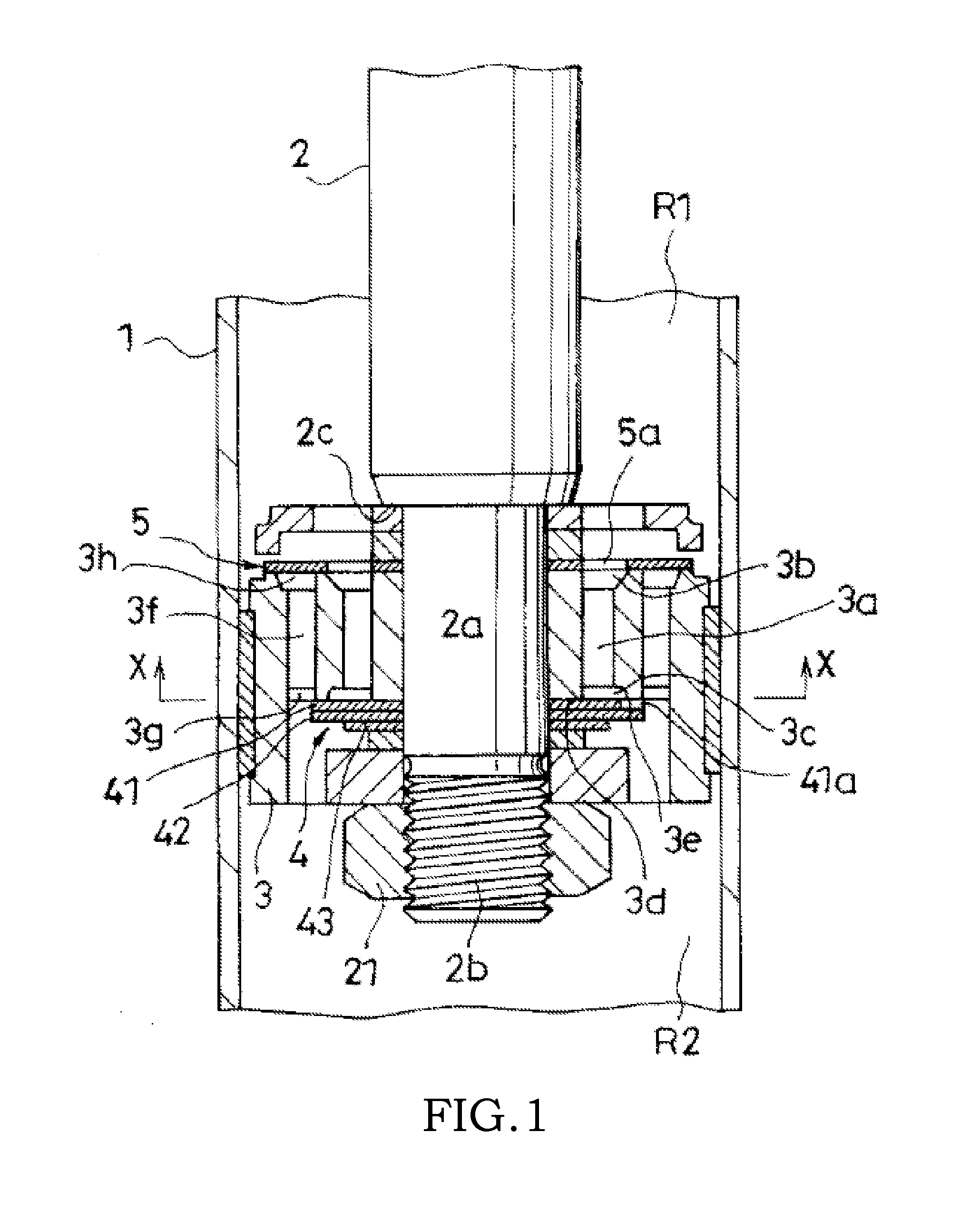
[0022]A damping valve according to an embodiment of the present invention will be described below with reference to drawing. The damping valve according to the embodiment of the present invention is used, for example, in a damping section in a shock absorber that is built into a suspension of a vehicle.

[0023]As shown in FIG. 1, the shock absorber has a cylinder 1 that contains, for example, working fluid that is working oil, a piston rod 2 that is inserted into the cylinder 1 so as to be capable of moving in and out, and a piston 3 that is held at a tip end portion 2a located at the lower end part of the piston rod 2 in FIG. 1 and that is slidably inserted into the cylinder 1 so as to be a partition that divides the space inside the cylinder 1 into a first chamber R1 and a second chamber R2. The working fluid may be liquid other than the working oil.

[0024]The shock absorber illustrated is of an upright type in which the cylinder 1 is linked with the axle side of a vehicle as a lower...


PUM


Abstract

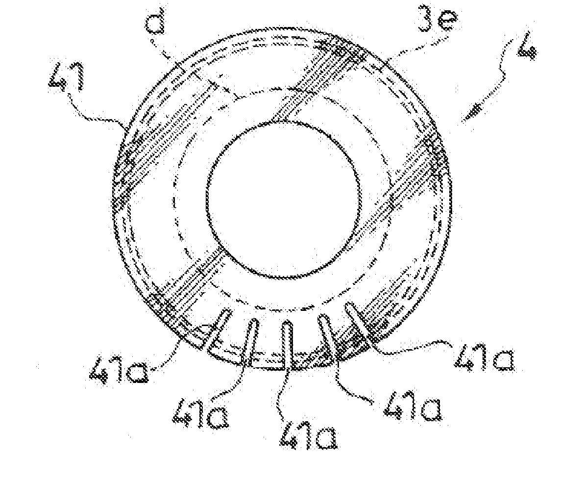
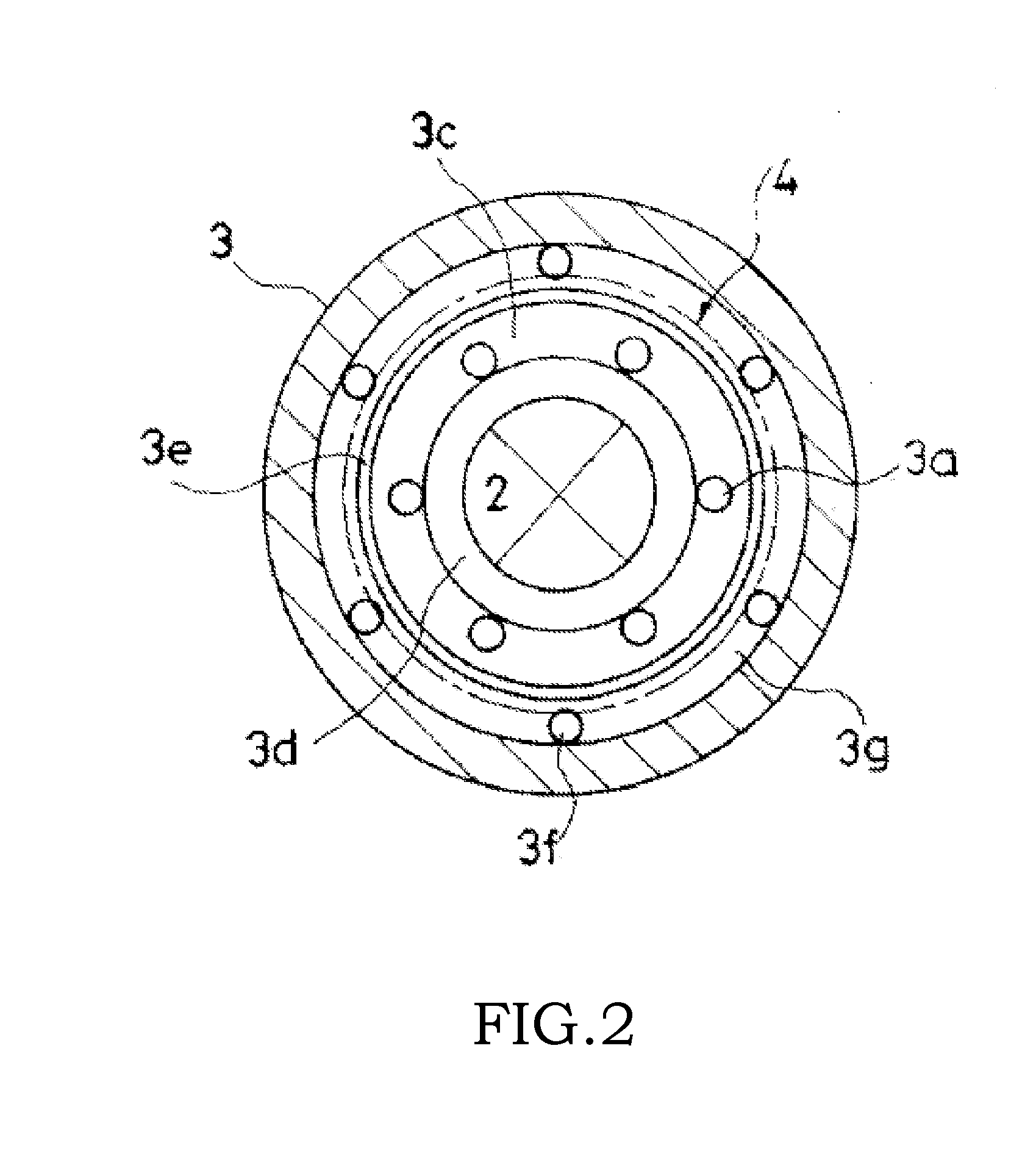
In a damping valve having a partition that separates a first chamber and a second chamber, a valve seat that is formed on an end surface of the partition facing the first chamber or the second chamber; and a leaf valve whose outer-circumferential end portion is separably seated on the valve seat, the leaf valve has a plurality of orifices for allowing working fluid to flow therethrough in the outer-circumferential end portion, and the plurality of orifices are concentrated in an arbitrary region along a circumferential direction in the outer-circumferential end portion of the leaf valve.

Description

TECHNICAL FIELD[0001]The present invention relates to a damping valve of a shock absorber that is built into a suspension of a vehicle.BACKGROUND ART[0002]From the viewpoint of ride comfort on a vehicle, it is preferred to set a shock absorber, which is built into a suspension of a vehicle, such that a damping force is actively generated when the shock absorber is expanded / contracted slowly with a large amplitude, and a damping force generated is suppressed when the shock absorber is expanded / contracted fast with a small amplitude, for example.[0003]JP2003-042214A discloses a damping valve that includes a piston, a ring-shaped valve seat that is formed on an end surface of the piston, and a ring-shaped leaf valve that is separably seated on the valve seat. The leaf valve has orifices formed by slits that are cut in the radial direction from an outer-circumferential end portion.[0004]In this damping valve, the piston separates a space in a cylinder containing working fluid into a fir...

Claims


Application Information

Patent Timeline
IPC IPC(8): F16F9/348F16F9/512F16K15/14
CPCF16F9/3484F16F9/512F16K15/147
Inventor IZEKI, TOSHIMICHIYAMADA, HIDEKIMIWA, MASAHIRO
Owner KYB CORP
Learn More