Furniture-foot assemblies

a technology for furniture and parts, applied in the field of furniture feet, can solve the problems of increasing the incidence and coverage of floor scraping, scratching or marring, and generating noise, so as to reduce the incidence of floor and reduce the noise of scraping, scratching or marring

Active Publication Date: 2010-07-29
HIWATT PROD
View PDF19 Cites 14 Cited by
  • Summary
  • Abstract
  • Description
  • Claims
  • Application Information

AI Technical Summary

Benefits of technology

[0011]One advantage of the furniture-foot assembly of the present invention is that use thereof is a relatively easy, efficient, and inexpensive way of adding a foot to the elbow of a sled-type leg of a chair or desk.
[0012]Another advantage of the furniture-foot assembly of the present invention is that it has a glide adapted to be removably mounted to the remainder of the assembly and reduce incidence of floor scraping, scratching, or marring and generation of noise.
[0013]Another advantage of the furniture-foot assembly of the present invention is that the bottom surface of the glide defines relatively less area upon which dirt, dust, sand, and other debris can gather.
[0014]Another advantage of the furniture-foot assembly of the present invention is that the glide may be replaced without replacing the remainder of the assembly.

Problems solved by technology

However, these legs suffer from many disadvantages.
More specifically, use of this type of leg generally facilitates a sliding motion across a relatively large surface area of the floor and, therefore, increases incidence and coverage of floor scraping, scratching, or marring and attendant noise.
This relatively greater amount of scraping, scratching, or marring, in turn, increases not only costs of stripping, waxing, and buffing the floor and other labor and material costs associated with maintaining the floor, but also the number of airborne particulates and, thus, pollutants in the room in which the corresponding chair or desk is used.
Furthermore, the bottom surface defines relatively more area upon which dirt, dust, sand, and other debris can gather, thus making this type of leg relatively more difficult, time-consuming, and, thus, expensive to clean and keep sanitary.
This debris can even be imbedded into the bottom surface of the leg such that the texture of the bottom surface becomes like sandpaper and, thus, scrapes, scratches, or mars the floor even more than it does otherwise.
In addition, when the chair or desk is moved along the floor, the frictional contact between this type of leg and the floor produces a perceptible, often irritating, noise.
In a classroom setting, especially in an elementary school where there are a substantial number of relatively young students moving or “scooting” their respective chairs and desks at any one time, this noise can be multiplied to a very significant level.
In such an especially wet environment, this type of leg—being made mostly or even entirely of metal—can rust and, hence, have a relatively shorter life, produce rust marks on the floor when the chair or desk is moved along the floor, and cause the legs of the chair or desk to be aesthetically displeasing.

Method used


Image

  • Furniture-foot assemblies
  • Furniture-foot assemblies
  • Furniture-foot assemblies

Examples


Embodiment Construction

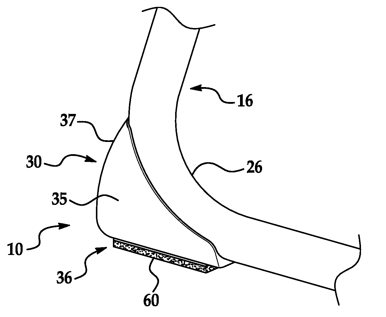
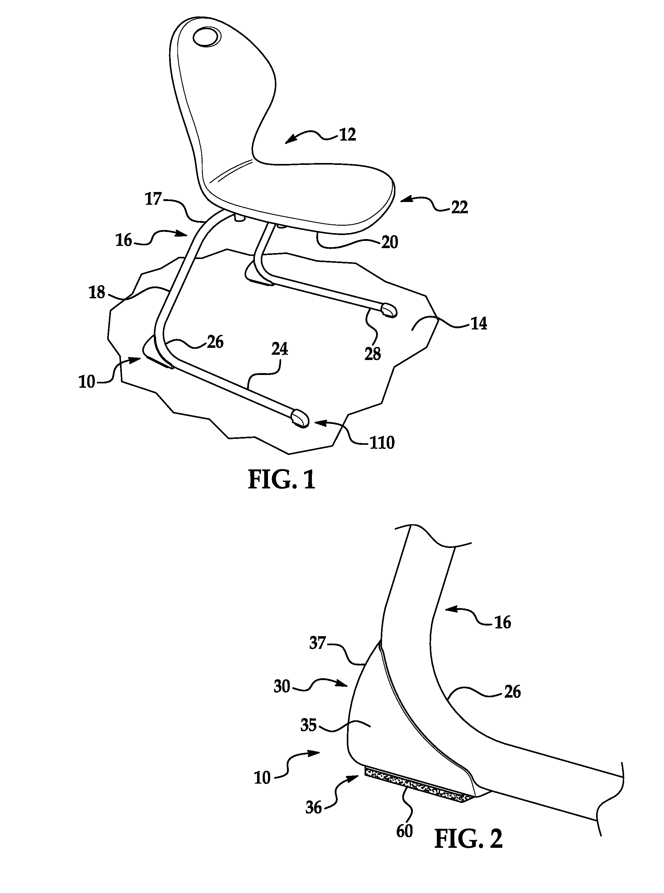
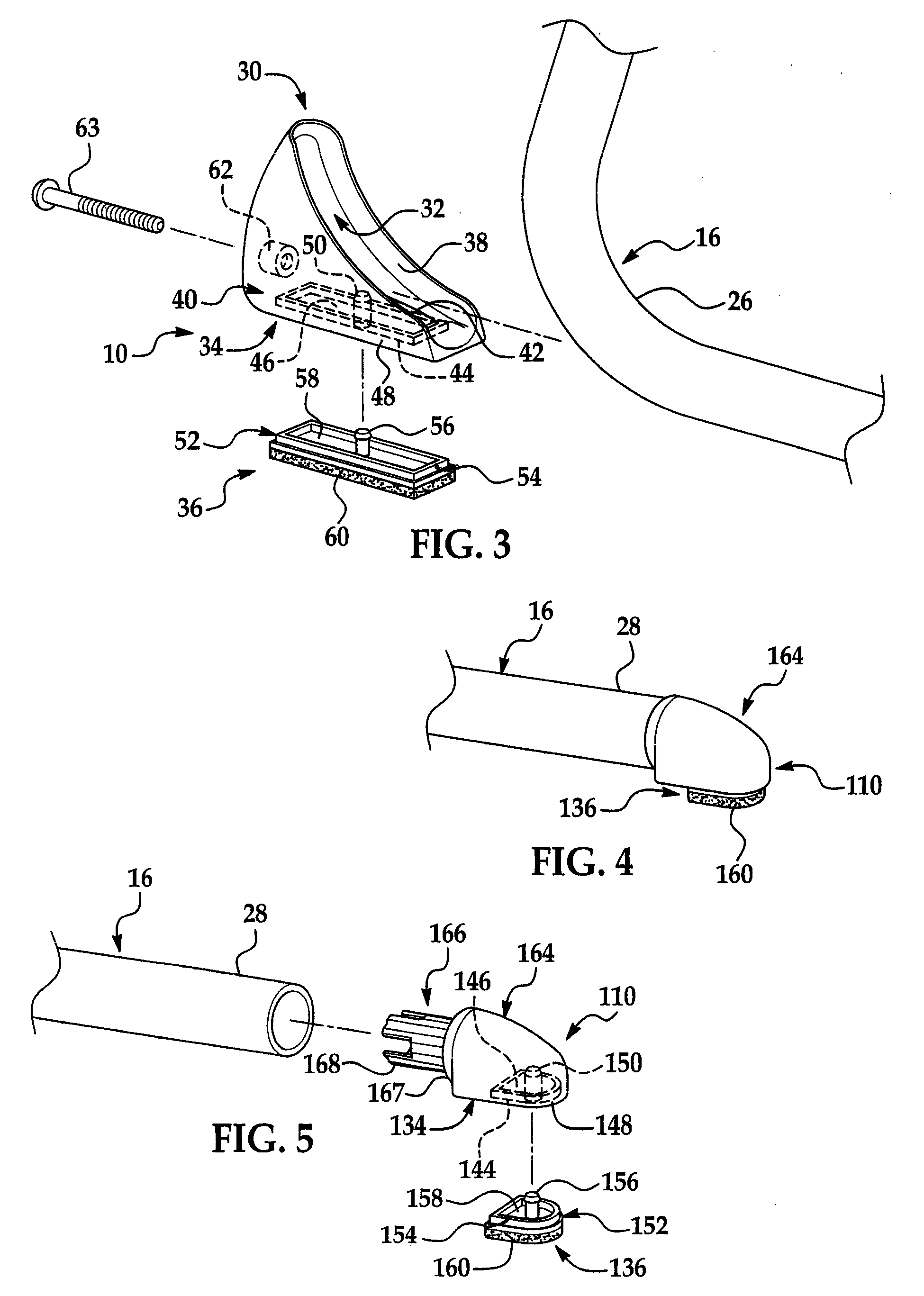
[0021]Referring now to the figures, where like numerals are used to designate like structure, first and second furniture-foot assemblies of the present invention are generally indicated respectively at 10, 110. Whereas the foot assembly 10 is adapted to be removably attached to the elbow of a sled-type leg of a piece of furniture (such as a chair), generally indicated at 12, that is adapted to be supported upon a surface of, say, a floor 14, the foot assembly 110 is adapted to be removably attached to the free end of the sled-type leg.

[0022]As shown in FIG. 1, a sled-type leg, generally indicated at 16, includes, in general, a cross-member 17 attached to and extending across a bottom surface 20 of a seat, generally indicated at 22, of the chair 12. The leg 16 also includes opposed, identical uppermost portions 18 integrally extending vertically from respective ends of the cross-member 17 toward the floor surface 14. The leg 16 also includes a pair of opposed, identical lowermost por...


PUM


Abstract

A foot assembly is adapted to be removably attached to the elbow of a sled-type leg of a piece of furniture that is adapted to be supported upon a surface. The furniture-foot assembly includes a body defining a hollow interior adapted to removably receive the elbow of the leg and a bottom exterior portion. A glide is adapted to be removably mounted to the bottom exterior portion of the body and supported upon the surface for gliding movement of the furniture-foot assembly relative to the surface.

Description

BACKGROUND OF THE INVENTION[0001]1. Field of the Invention[0002]The present invention relates, in general, to a foot attachable to a leg of a piece of furniture and, in particular, to foot assemblies removably attachable respectively to the elbow and free end of each sled-type leg of a chair or desk.[0003]2. Description of the Related Art[0004]The free end of each leg of a piece of furniture often includes a cap, foot, glide, or the like. In many institutionalized settings, such as in a school or other educational facility, the foot disposed on the corresponding free ends of the respective legs of a piece of furniture are designed to allow easy sliding of a chair or desk, for instance, upon a surface such as a floor. More specifically, the foot is designed to increase the amount of surface-area contact, but reduce the amount of frictional contact, between the legs and the floor.[0005]One type of chair commonly employed in schools generally includes a pair of opposed, identical sled-...

Claims


Application Information

Patent Timeline
Patent Type & Authority Applications(United States)
IPC IPC(8): A47G29/00A47C31/00
CPCA47B91/06Y10T16/21A47C7/002
Inventor CHASE, JOHN
Owner HIWATT PROD
Why Eureka
Try Eureka