
Methods of forming asymmetric recesses and gate structures that fill such recesses and related methods of forming semiconductor devices that include such recesses and gate structures

a technology of asymmetric recesses and gate structures, applied in the field of semiconductor devices, can solve problems such as alignment errors and generating bowing defects, and achieve the effects of reducing the noise generated between the asymmetric gate structures, reducing leakage current through the junction, and improving characteristics

Inactive Publication Date: 2009-07-14
SAMSUNG ELECTRONICS CO LTD
View PDF14 Cites 15 Cited by
  • Summary
  • Abstract
  • Description
  • Claims
  • Application Information

AI Technical Summary

Benefits of technology

[0007]Some embodiments of the present invention provide an asymmetric recessed gate structure that may fill an asymmetric recess.
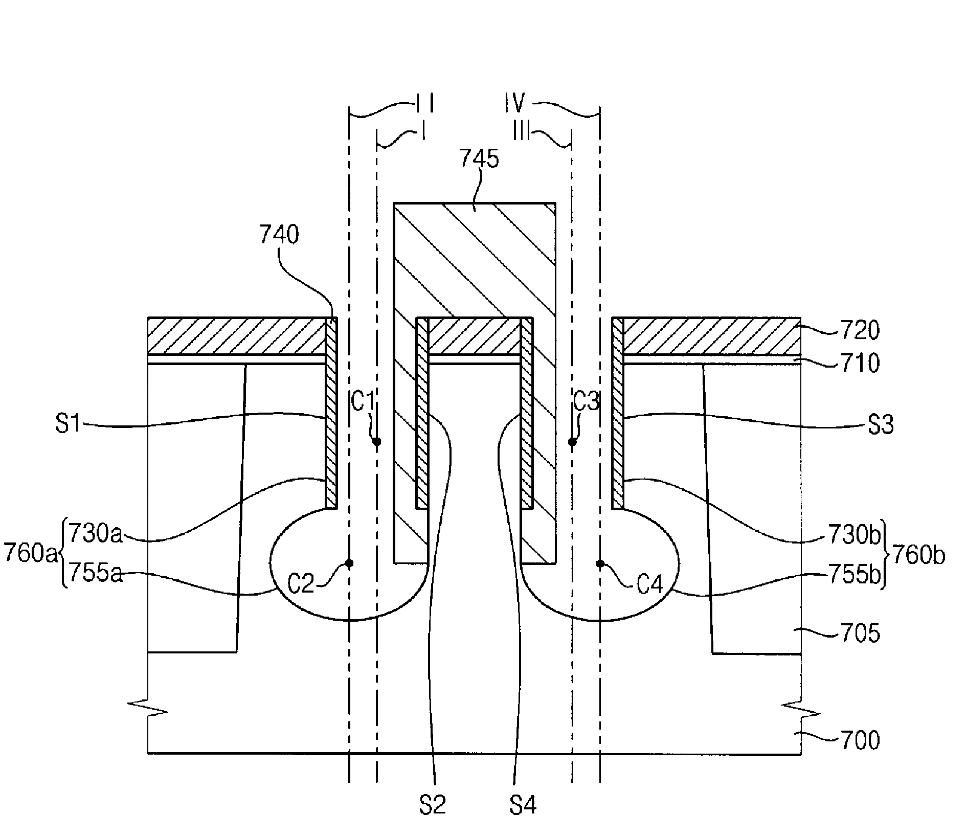
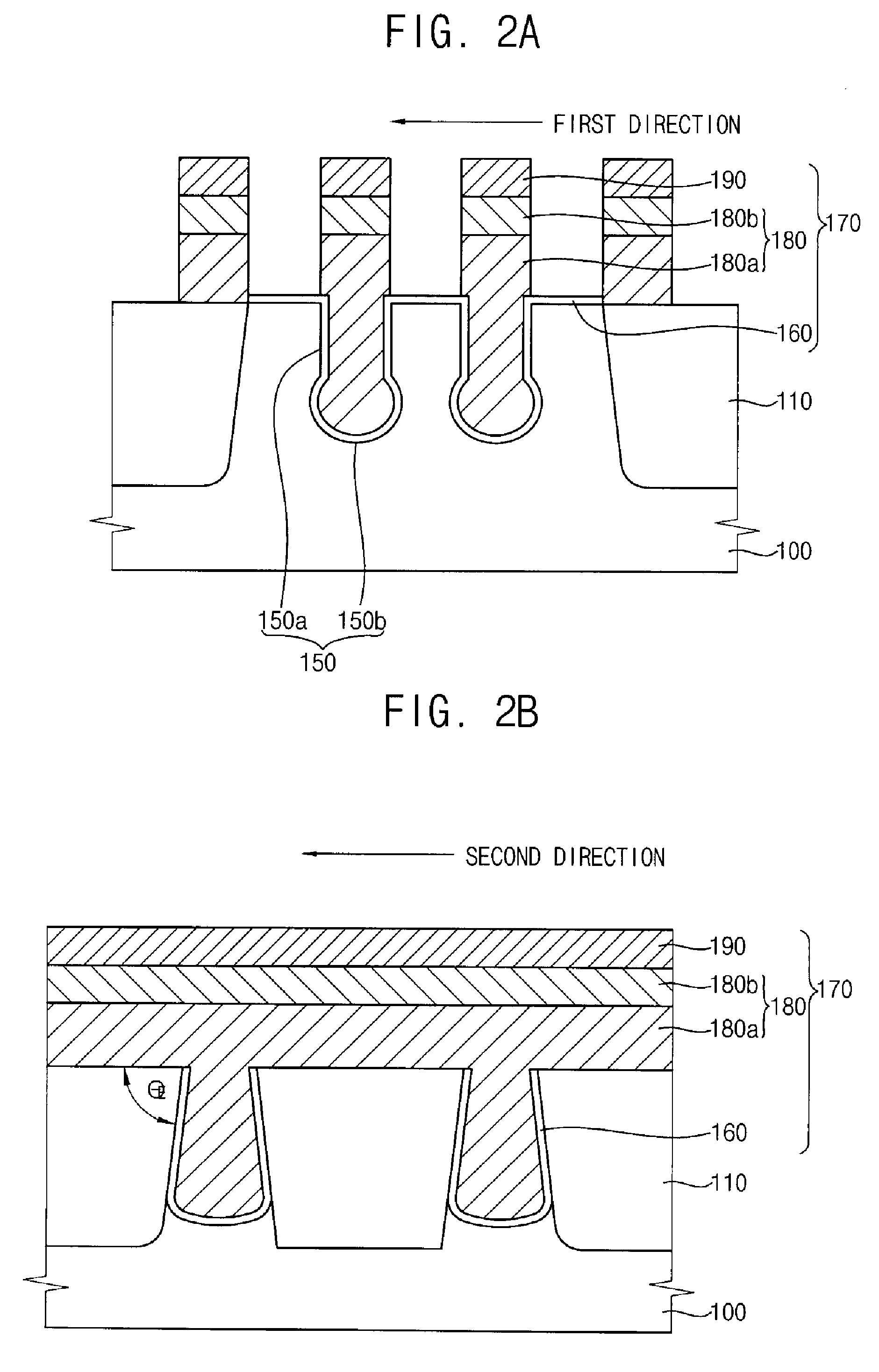
[0022]According to some embodiments of the present invention, a lower portion of an asymmetric gate structure has an extended cross section with a substantial circular shape, a substantial oval shape or a substantial track shape. The term “track shape” is defined herein to mean any generally circular or oval shape and that may or may not include one or more generally linear sections. Thus, a length of a channel formed around the lower portion of the asymmetric gate structure may be also extended. In addition, because the lower portion of the asymmetric gate structure is extended toward an isolation layer, a width of a junction formed between the isolation layer and the lower portion of the asymmetric gate structure may decrease. Thus, a leakage current through the junction may decrease. Furthermore, an interval between the asymmetric gate structures may be kept substantially constant. Thus, a noise unfortunately generated between the asymmetric gate structures may decrease. As a result, a semiconductor device including the asymmetric gate structure may have improved characteristics such as a reduced leakage current or an extended retention time.

Problems solved by technology

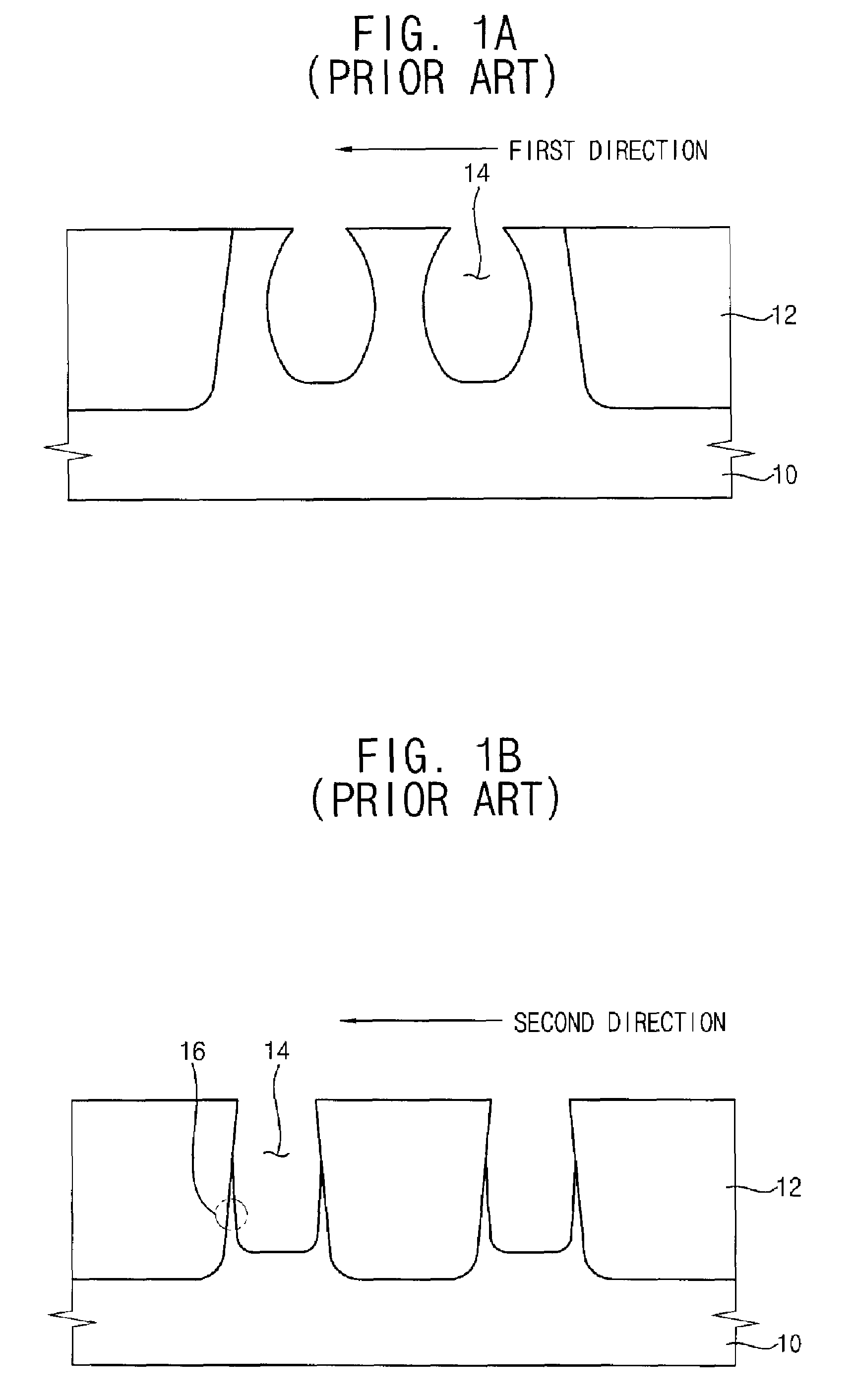
The wet etch, however, may recess a sidewall of the recess 14 toward the isolation layer 14, thereby generating a bowing defect.
In addition, a critical dimension (CD) of the recess 14 may increase in the wet etching process which can result in alignment errors in succeeding processes.

Method used


Image

  • Methods of forming asymmetric recesses and gate structures that fill such recesses and related methods of forming semiconductor devices that include such recesses and gate structures
  • Methods of forming asymmetric recesses and gate structures that fill such recesses and related methods of forming semiconductor devices that include such recesses and gate structures
  • Methods of forming asymmetric recesses and gate structures that fill such recesses and related methods of forming semiconductor devices that include such recesses and gate structures

Examples


Embodiment Construction

[0035]Embodiments of the present invention will be described with reference to the accompanying drawings. The present invention may, however, be embodied in many different forms and should not be construed as limited to the embodiments set forth herein. Rather, the embodiments are provided so that disclosure of the present invention will be thorough and complete, and will fully convey the scope of the present invention to those skilled in the art. The principles and features of this invention may be employed in varied and numerous embodiments without departing from the scope of the present invention. In the drawings, the size and relative sizes of layers and regions may be exaggerated for clarity. The drawings are not to scale. Like reference numerals designate like elements throughout the drawings.

[0036]It will also be understood that when an element or layer is referred to as being “on”, “connected to” and / or “coupled to” another element or layer, the element or layer may be direc...


PUM


Abstract

In a method of forming an asymmetric recess, an asymmetric recessed gate structure filling the asymmetric recess, a method of forming the asymmetric recessed gate structure, a semiconductor device having the asymmetric recessed gate structure and a method of manufacturing the semiconductor device, a semiconductor substrate is etched to form a first sub-recess having a first central axis. A second sub-recess is formed under the first sub-recess. The second sub-recess is in communication with the first sub-recess. The second sub-recess has a second central axis substantially parallel with the first central axis. The second central axis is spaced apart from the first central axis.

Description

CROSS REFERENCE TO RELATED APPLICATION[0001]This is a continuation-in-part of U.S. patent Ser. No. 11 / 285,558 filed Nov. 22, 2005, which claims priorities under 35 USC § 119 to Korean Patent Application No. 2004-98014 filed on Nov. 26, 2004, and to Korean Patent Application No. 2005-65777 filed on Jul. 20, 2005. This application claims benefit of priority under 35 U.S.C. § 119 to Korean Patent Application No. 2005-69061 filed on Jul. 28, 2005, the disclosure of which is incorporated herein by reference.FIELD OF THE INVENTION[0002]The present invention relates to semiconductor devices and, more particularly, to methods of forming recesses and gate structures that fill such recesses and related semiconductor devices that include such recesses and gate structures.BACKGROUND OF THE INVENTION[0003]As the integration of semiconductor devices has increased, the line width and other critical dimensions of patterns in the devices have decreased. Thus, techniques for forming finer, more preci...

Claims


Application Information

Patent Timeline
Patent Type & Authority Patents(United States)
IPC IPC(8): H01L21/76
CPCH01L29/66621H01L29/7834H01L29/66659
Inventor PARK, SE-KEUN
Owner SAMSUNG ELECTRONICS CO LTD
Learn More