Single Stage Dual Chambered Passenger Airbag

a passenger airbag and dual chamber technology, applied in the direction of pedestrian/occupant safety arrangement, vehicle components, vehicular safety arrangments, etc., can solve the problems of difficult design of multi-chamber airbags, difficult to design multi-chamber airbags, and high cost of dual-stage airbags or on

Active Publication Date: 2015-02-05
JOYSON SAFETY SYST ACQUISITION LLC
View PDF19 Cites 1 Cited by
  • Summary
  • Abstract
  • Description
  • Claims
  • Application Information

AI Technical Summary

Benefits of technology

[0014]In general, the present invention includes an airbag containing a divider that forms a first chamber and a second chamber, wherein the divider contains a first valve assembly controlling the flow of gas from the first chamber to the second chamber. The invention further includes a second valve assembly within the first chamber that is operatively dependent on the first valve assembly. The term “operatively dependent” is understood to mean that the second valve assembly will be open or will be closed based on a condition precedent of the first valve assembly. In the present context, for example, the first valve assembly may attenuate or occlude gas flow from the second chamber to the first chamber based on a pressure increase within the second chamber. When that occurs, the second valve assembly is prompted to close based on a resultant increase in pressure within the first chamber. The dual valve assemblies eliminate the need for a dual stage inflator, by providing a dynamic and substantially similar protection with gas produced from a single stage inflator.

Problems solved by technology

However, these cushion designs do not differentiate between these different regions with regard to the stiffness or resistance of the various portions of the airbag to contact with each region.
Due to the differences in body part masses and the dynamics of contact between the occupant and the cushion, it has proven difficult to design a multi-chamber airbag which provides optimum protection for each portion of the body contacting the airbag.
Although effective in these regards, a dual stage inflator is relatively more expensive than a single stage inflator or one that only includes a single combustion chamber with one stage of combustion.

Method used


Image

  • Single Stage Dual Chambered Passenger Airbag
  • Single Stage Dual Chambered Passenger Airbag
  • Single Stage Dual Chambered Passenger Airbag

Examples


Embodiment Construction

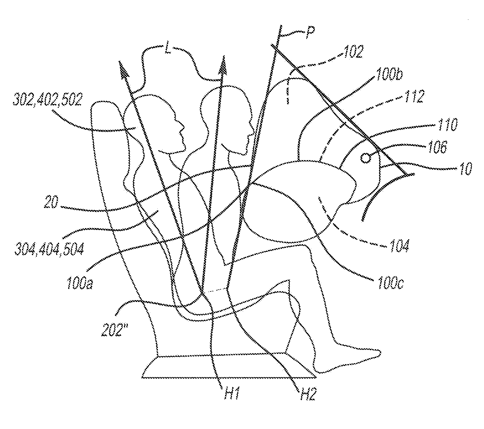
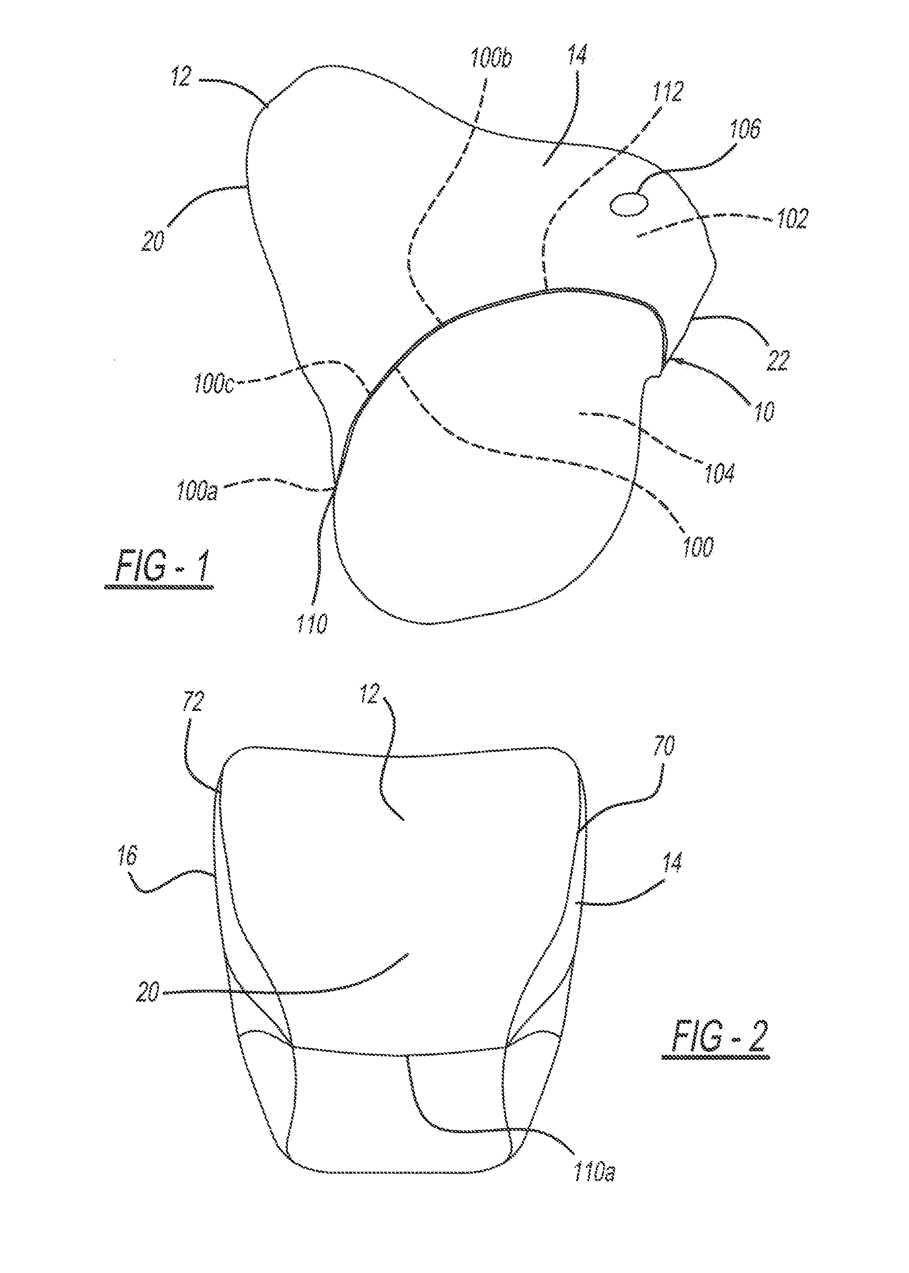
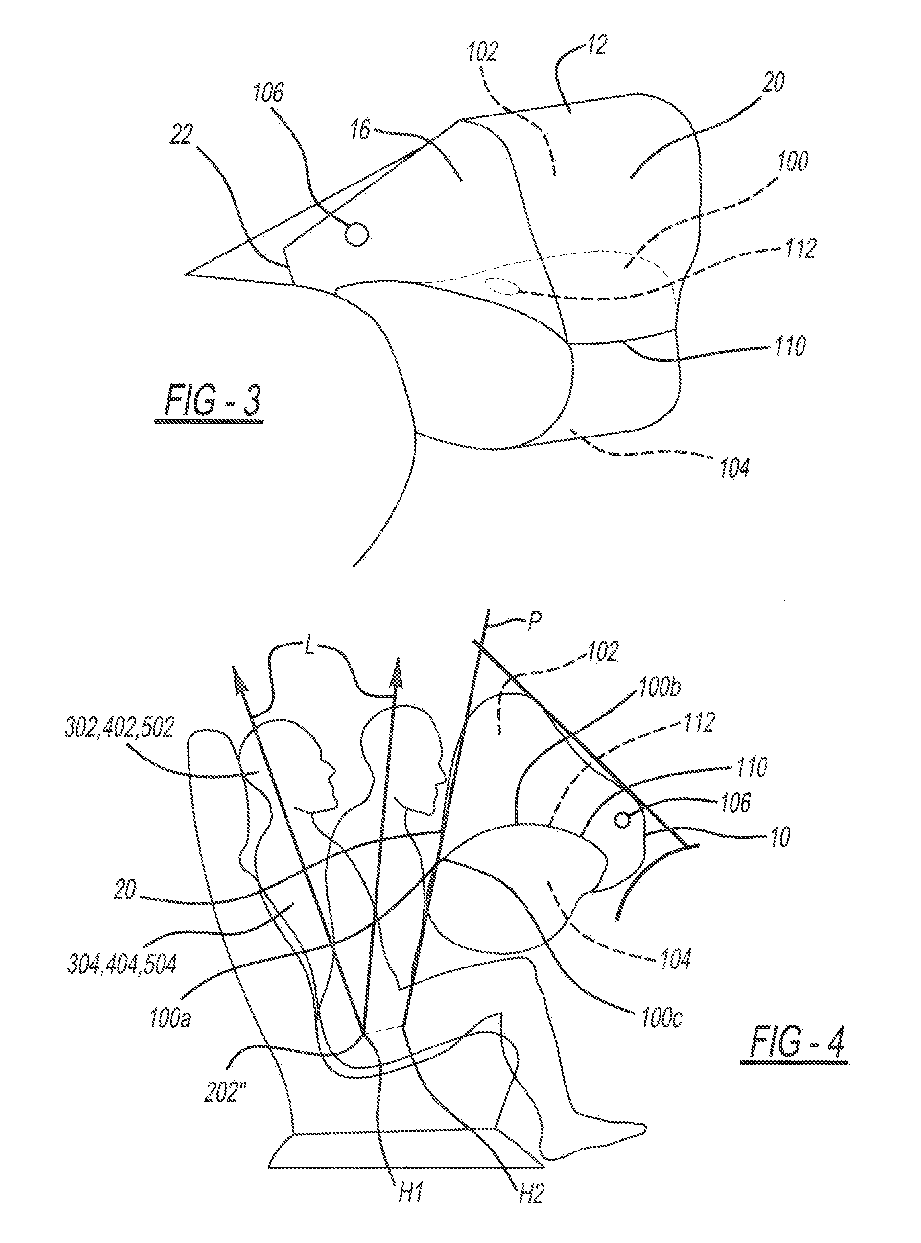
[0047]Embodiments of the present invention will be described below with reference to the drawings. One of ordinary skill in the art will appreciate the various aspects of airbag design, construction and operation applicable to the embodiments of the present invention described herein. U.S. Pat. Nos. 6,886,857, 7,857,347, 8,128,124, 7,931,299, and 8,322,748, for example, describe many such aspects and are incorporated herein by reference in their entirety, but not by way of limitation.

[0048]FIGS. 1-4 are views of a passenger-side airbag 10 (in an inflated state) according to an embodiment of the present invention. The airbag embodiment shown in FIGS. 1-4 is formed from three panels. Specifically, the airbag is formed of a main panel 12, a right side (when viewing the airbag from a seated position) panel 14, and a left side panel 16 opposite the right side panel 14. Each of the side panels 14, 16 is generally planar (when the airbag 10 is not inflated). The main panel 12 connects the ...


PUM


Abstract

An airbag includes at least one panel defining an interior of the airbag, and a divider positioned in the interior so as to divide the interior into a first chamber and a second chamber. A first valve assembly is operatively coupled to the divider for controlling the gas flow between the first chamber and the second chamber. A second valve assembly is fixed within the first chamber and fluidly communicates with an exterior of the airbag. The second valve assembly is operably dependent on the first valve assembly, thereby dynamically controlling the inflation profile of the airbag.

Description

CROSS-REFERENCE TO RELATED APPLICATIONS[0001]This application claims the benefit of U.S. Provisional Application Ser. No. 61 / 861,045, filed on Aug. 1, 2013, the disclosure of which is incorporated herein by reference in its entirety.BACKGROUND OF THE INVENTION[0002]The present invention relates a passenger airbag, which is filled with gas during an emergency situation such as, for example, a frontal or side impact.[0003]Current airbag cushion designs may include multiple chambers and may incorporate an inter-chamber venting system that allows gas to flow from one chamber to another. These cushions are configured to rapidly contact a vehicle occupant when inflated, to limit movement of the passenger head, neck and thoracic regions. However, these cushion designs do not differentiate between these different regions with regard to the stiffness or resistance of the various portions of the airbag to contact with each region.[0004]Research has shown that the masses of the various body po...

Claims


Application Information

Patent Timeline
Patent Type & Authority Applications(United States)
IPC IPC(8): B60R21/233B60R21/26
CPCB60R21/233B60R2021/26094B60R21/26B60R2021/23382
Inventor ANDERSON, CHRISTOPHER L.
Owner JOYSON SAFETY SYST ACQUISITION LLC
Why Eureka
Try Eureka