Imaging system for imaging a periodically moving object

a technology of periodic motion and imaging system, which is applied in the direction of applications, ultrasonic/sonic/infrasonic image/data processing, and catheters. it can solve the problem of reducing the quality of controlling the ablation procedure based on the m-mode image, and achieve the effect of less motion artifacts

Active Publication Date: 2015-02-05
KONINKLJIJKE PHILIPS NV
View PDF9 Cites 8 Cited by
  • Summary
  • Abstract
  • Description
  • Claims
  • Application Information

AI Technical Summary

Benefits of technology

[0004]It is an object of the present invention to provide an imaging system, an imaging method and an imaging computer program for imaging a periodically moving object, which allows providing an image of the object comprising less motion artifacts.

Problems solved by technology

Due to cardiac motion the M-mode image may comprise motion artifacts, which can reduce the quality of controlling the ablation procedure based on the M-mode image.

Method used


Image

  • Imaging system for imaging a periodically moving object
  • Imaging system for imaging a periodically moving object
  • Imaging system for imaging a periodically moving object

Examples


Embodiment Construction

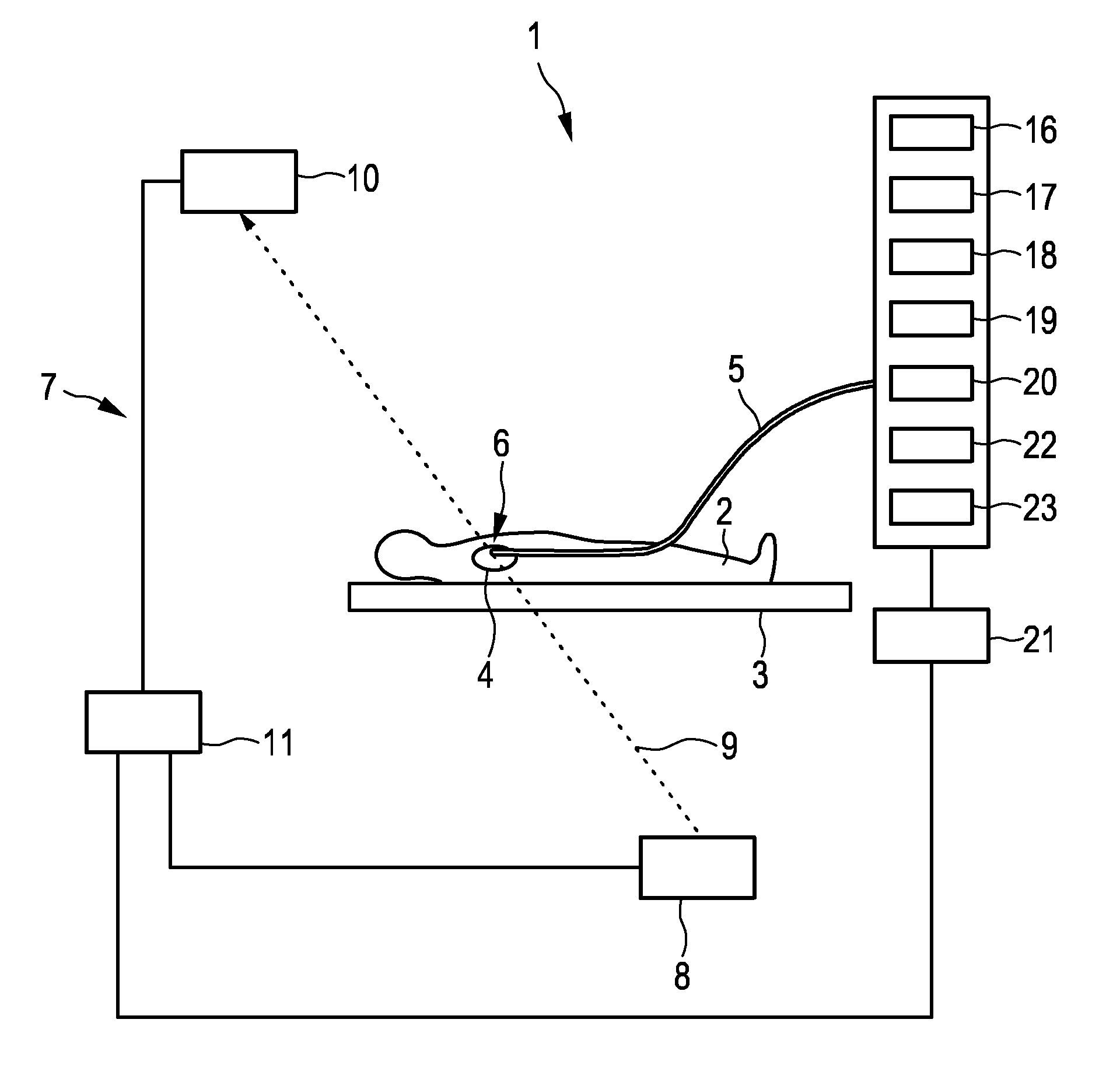
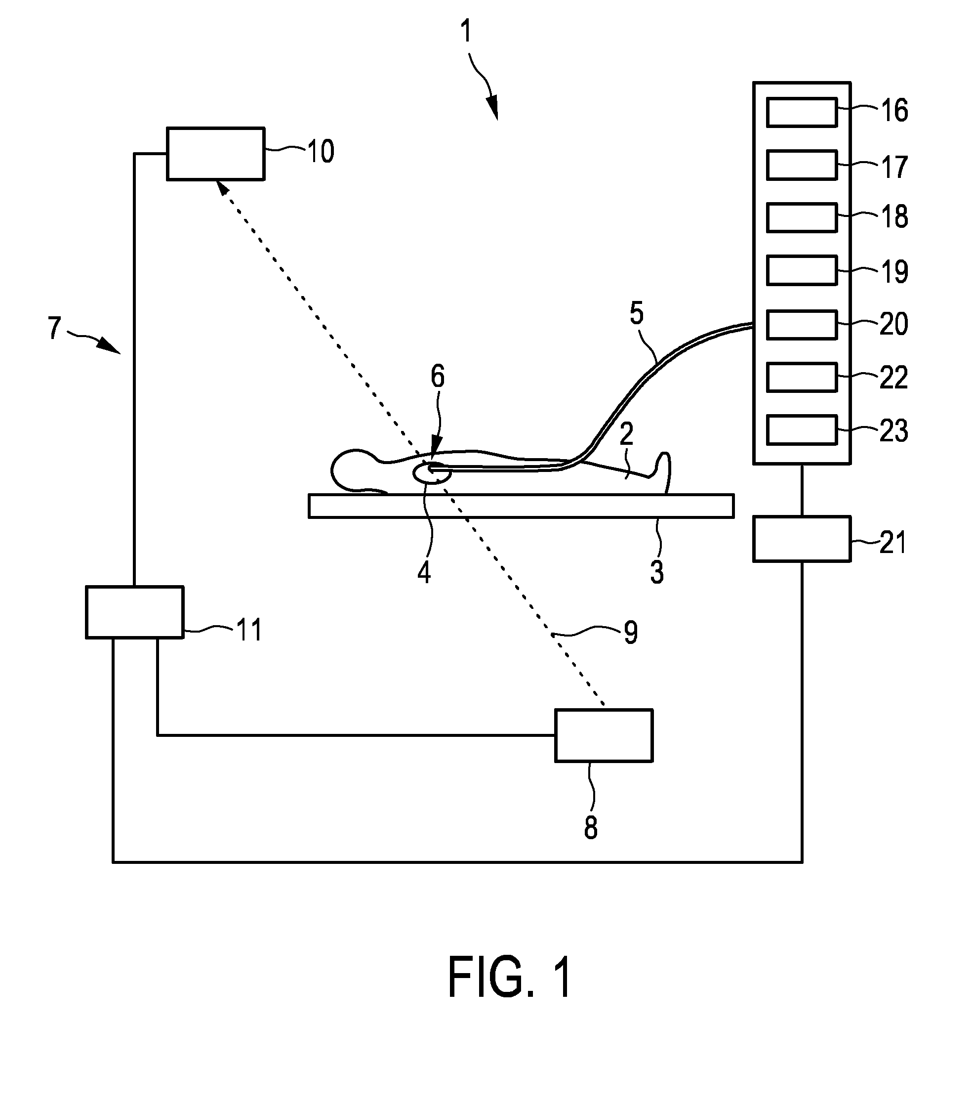
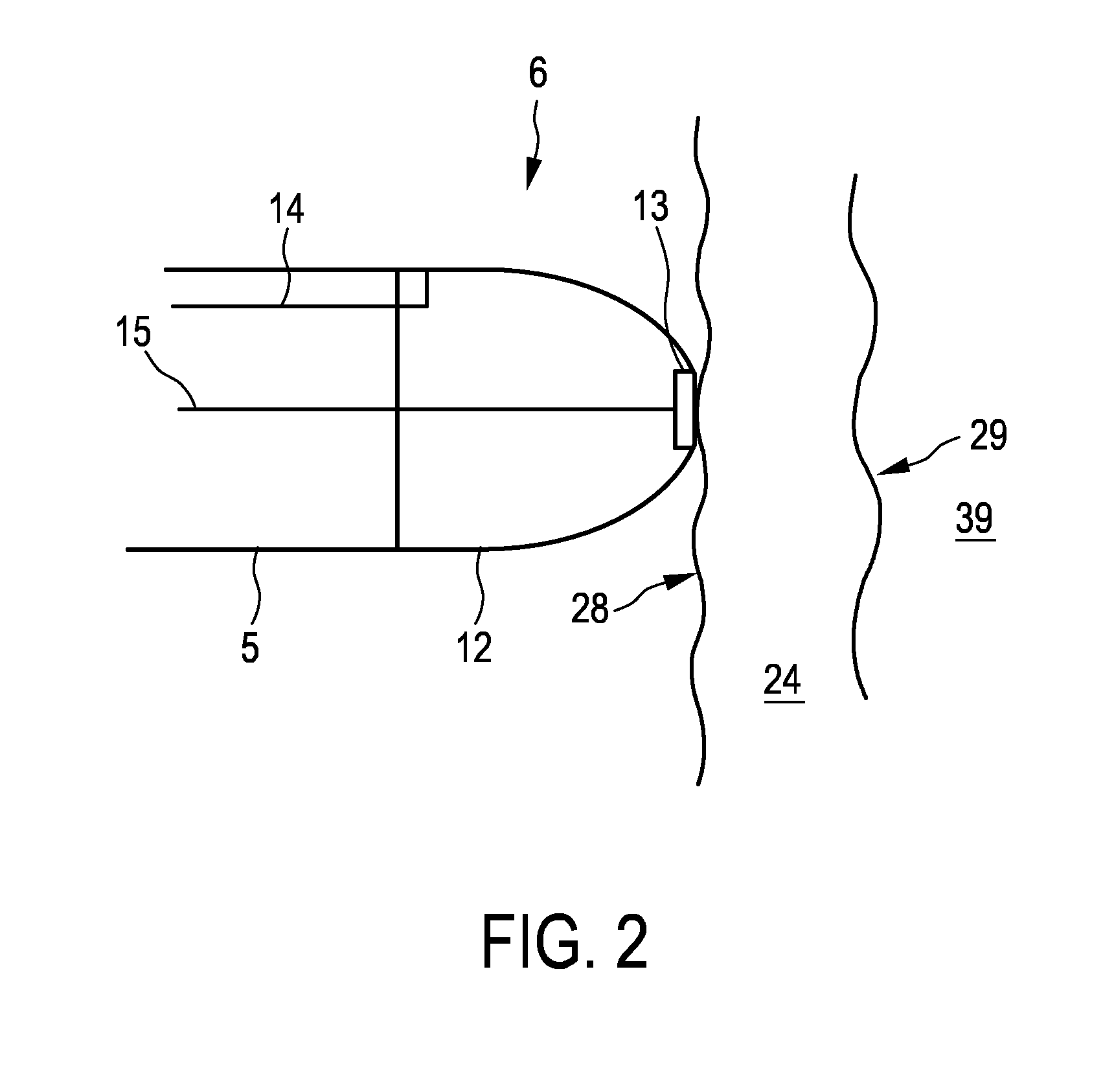
[0060]FIG. 1 shows schematically and exemplarily an imaging system 1 for imaging a periodically moving object. In this embodiment, the periodically moving object is a tissue wall of a heart 4 of a person 2 lying on a table 3. The imaging system 1 comprises a catheter 5 with a catheter tip 6, which is shown in more detail in FIG. 2.

[0061]The catheters tip 6 comprises an ultrasound transducer 13, which is connected to an ultrasound control unit 16 for controlling the ultrasound transducer 13 via an electrical connection 15 like an insulated wire. The ultrasound transducer 13 and the ultrasound control unit 16 form an ultrasound signals providing unit for providing ultrasound signals of the tissue wall 24 for different times. In particular, the ultrasound transducer 13 and the ultrasound control unit 16 are adapted to send ultrasound pulses into the tissue wall 24, to receive echo series after the ultrasound pulses have been reflected by the tissue wall 24 and to generate A-lines depen...


PUM


Abstract

The invention relates to an imaging system for imaging a periodically moving object. An assigning unit (18) assigns ultrasound signals like A-lines to motion phases based on a provided phase signal, wherein an ultrasound images generation unit (19) generates several ultrasound images like gated M-mode images for the different motion phases based on the ultrasound signals assigned to the respective motion phase. A selecting unit (20) is used to select an ultrasound image from the generated ultrasound images, wherein a display unit (21) displays the selected ultrasound image. The selected ultrasound image corresponds therefore to a single motion phase only such that motion artifacts in the displayed ultrasound image are reduced. The imaging system is particularly useful for, for instance, monitoring cardiac ablation procedures.

Description

FIELD OF THE INVENTION[0001]The invention relates to an imaging system, an imaging method and an imaging computer program for imaging a periodically moving object.BACKGROUND OF THE INVENTION[0002]US 2012 / 004547 A1 discloses a monitoring apparatus for monitoring an ablation procedure. The monitoring apparatus comprises an ultrasound image providing unit for providing an M-mode image of cardiac tissue during an ablation procedure such that a physician can control the ablation procedure based on the M-mode image.[0003]Due to cardiac motion the M-mode image may comprise motion artifacts, which can reduce the quality of controlling the ablation procedure based on the M-mode image.SUMMARY OF THE INVENTION[0004]It is an object of the present invention to provide an imaging system, an imaging method and an imaging computer program for imaging a periodically moving object, which allows providing an image of the object comprising less motion artifacts.[0005]In a first aspect of the present an...

Claims


Application Information

Patent Timeline
Patent Type & Authority Applications(United States)
IPC IPC(8): A61B8/08A61B8/12A61B8/00
CPCA61B8/5276A61B8/486A61B8/0883A61B8/465A61B8/12A61B8/0858A61B8/463A61B8/5284A61B18/1492A61B2018/00011A61B2018/00982A61B2018/00994A61B2090/3782A61B2090/3784A61B2090/378
Inventor BELT, HARM JAN WILLEMFOKKENROOD, STEVEN ANTONIE WILLEMZUO, FEIKOLEN, ALEXANDER FRANCISCUSDELADI, SZABOLCSHARKS, GODEFRIDUS ANTONIUS
Owner KONINKLJIJKE PHILIPS NV
Why Eureka
Try Eureka