
Systems and Methods for Estimating Fluid Breakthrough Times at Producing Well Locations

a technology of fluid breakthrough time and production well, which is applied in the field of estimating fluid breakthrough time at producing well locations, can solve the problems of inherently biased production data and noisy data

Inactive Publication Date: 2015-02-05
LANDMARK GRAPHICS
View PDF5 Cites 7 Cited by
  • Summary
  • Abstract
  • Description
  • Claims
  • Application Information

AI Technical Summary

Benefits of technology

The present invention provides a way to estimate how long it will take for fluid to break through at the well location based on simulations of how the fluid will spread. This helps to improve the production of oil and gas from the well.

Problems solved by technology

Despite the progress in HM technology, it is still by far the most time-consuming aspect of the model building / simulation study and the HM workflow faces many difficulties, which include:i) non-linear results between the production response and reservoir parameters;ii) non-unique solutions, which require a definition of some semblance of “uniqueness”;iii) the relative impact of key parameters may not be obvious;iv) constraints are not bounded and uncertainties and in the variables are seldom known; andv) the production data may be noisy and inherently biased.

Method used


Image

  • Systems and Methods for Estimating Fluid Breakthrough Times at Producing Well Locations
  • Systems and Methods for Estimating Fluid Breakthrough Times at Producing Well Locations
  • Systems and Methods for Estimating Fluid Breakthrough Times at Producing Well Locations

Examples


example

[0052]Referring now to the synthetic 2D permeability model in FIG. 4A, the observed (measured) water-cut curves for the configuration model in FIG. 4A are given in FIGS. 7A, 7B, 7C, and 7D for each of the four production wells (P1, P2, P3, and P4).

[0053]The date / time data points on the x-axis in FIGS. 7A-7D correspond with the physical dates associated with the water injection plan (water breakthrough data points) presented in Table 1 below:

TABLE 1Data pointPhysical Date (dd / mm / yyyy)117 / 9 / 200024 / 6 / 2001319 / 2 / 200246 / 10 / 2002524 / 7 / 200369 / 4 / 2004725 / 12 / 2004811 / 9 / 2005

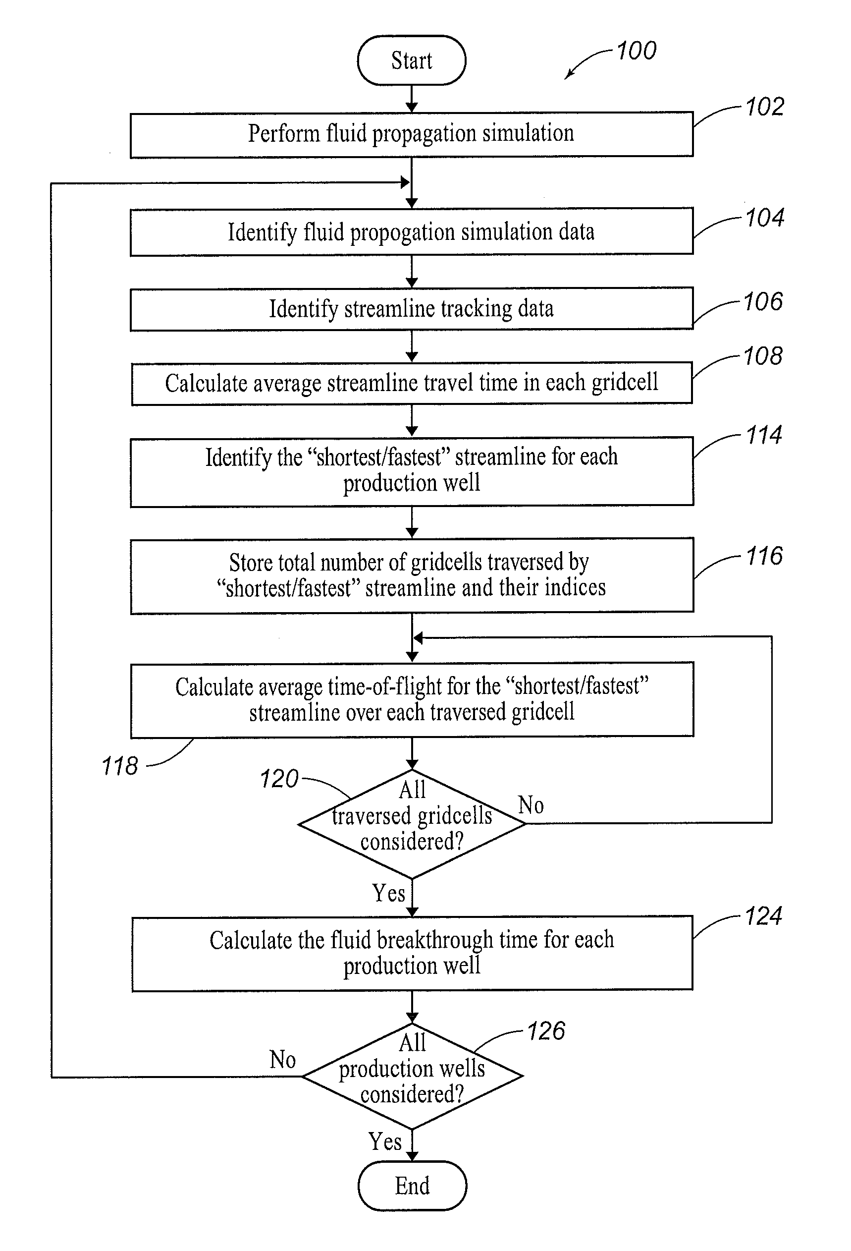
[0054]The observed water breakthrough times deduced from FIG. 4A, are given in Table 2 below. Moreover, Table 2 lists the water invasion times calculated by the FPS algorithm the water breakthrough times (TB7) calculated using the proposed method in FIG. 1 and the uncertainty associated with result obtained by the proposed method in FIG. 1.

TABLE 2Invasion TBT by Observed TBTTimeproposedUncertaintyProducer(days)(iterations)meth...


PUM


Abstract

Systems and methods for estimating fluid breakthrough times at producing well locations based on fluid propagation simulation.

Description

CROSS-REFERENCE TO RELATED APPLICATIONS[0001]NoneSTATEMENT REGARDING FEDERALLY SPONSORED RESEARCH[0002]Not applicable.FIELD OF THE INVENTION[0003]The present invention generally relates to estimating fluid breakthrough times at producing well locations. More particularly, the invention relates to estimating fluid breakthrough times at producing well locations based on fluid propagation simulations.BACKGROUND OF THE INVENTION[0004]Various systems and methods are known for estimating the fluid breakthrough time at a producing well location, including history matching (HM). History Matching (HM) is a systematic procedure of altering a reservoir simulation model to reproduce the dynamic field response. In HM applications and conditioning reservoir models to production data, the main objectives are a) integration of production data into reservoir models; b) flexibility, cost-effectiveness and computational efficiency; and c) full utilization of dynamic data.[0005]In the last decade, HM t...

Claims


Application Information

Patent Timeline
Patent Type & Authority Applications(United States)
IPC IPC(8): E21B47/10
CPCE21B47/10E21B43/20E21B49/00Y02A10/40
Inventor MAUCEC, MARKO
Owner LANDMARK GRAPHICS
Learn More