

Control of fluid flow during treatment of subterranean sites using well fluid injection
A technology for ground and well treatment, applied in the direction of production fluid, wellbore/well components, drilling composition, etc., which can solve the problems of low sweep efficiency and other issues
- Summary
- Abstract
- Description
- Claims
- Application Information
AI Technical Summary
Problems solved by technology
Method used
Image

Examples
example
[0032] The invention will be further illustrated in the following examples. It should be understood, that these Examples, while indicating preferred embodiments of the invention, are given by way of illustration only. From the above discussion and these examples, those skilled in the art can ascertain the essential characteristics of the present invention, and without departing from the scope of the present invention, can make various changes and modifications to the present invention, so that it is applicable to various application and conditions.
[0033] abbreviation used in examples
[0034] "h" means hours; "L" means liters; "°C" means degrees Celsius; "mg" means milligrams; "mm" means millimeters; "kg" means kilograms; "ppt" means parts / "mM" means millimole per liter; "%" means percentage; "min" means minute; "mL / min means milliliter / minute; "D" means day; "μg / L" means Refers to micrograms per liter; "nM" refers to nanomoles per liter; "μM" refers to micromoles per...
example 1
[0035] Example 1 (predictive)
[0036] Determining breakthrough time in producing wells
[0037] The breakthrough time of each production well was determined using a chemical tracer such as fluorescein dye sodium salt, commonly known as sodium fluorescein (CAS518-47-8, part number A833-500, Fisher Scientific , 2000 Park Lane Drive, Pittsburgh, PA 15275).
[0038] Sodium fluorescein (2.7 kilograms, kg) was added to a tank containing 9,000 L of water. Shut off the normal flow of injection water to the injection well to be tested. The water treated with sodium fluorescein was injected into the injection well after 7.2 hours, and the injection rate was equal to 1,250L / h, which is a normal injection flow rate. When the injection of 9,000 L of sodium fluorescein solution was completed, the normal water injection flow rate of 30,000 L / D was resumed. After initiation of sodium fluorescein injection, samples were taken from associated production wells at various time intervals,...
example 2
[0039] Example 2 (predictive)
[0040] Inoculate subterranean sites without microbial seed loss
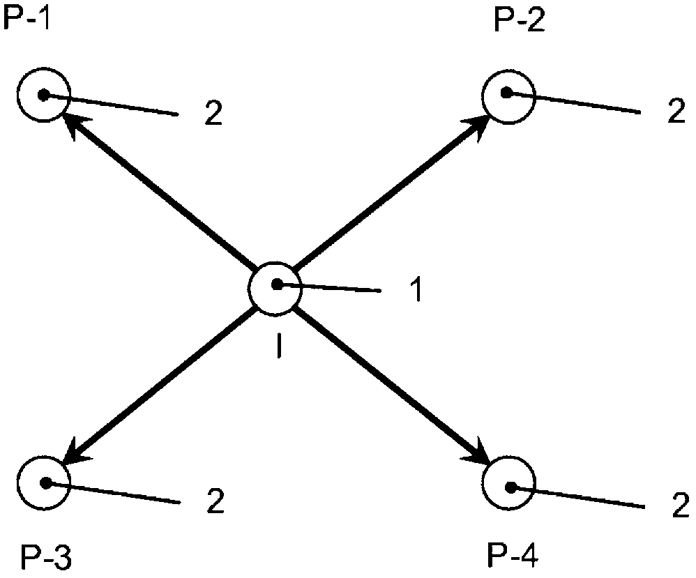
[0041] In this example, the injection and production wells at the subterranean site are arranged as figure 1 The inverse five-point pattern shown. For the purposes of this example, assume that producer P2 has the shortest breakthrough time, followed by producer P4, which has the second shortest breakthrough time. Microbial inoculum suspensions were prepared by forming in 6,000L tanks a nutritional chemical fluid suitable for utilization by specific microorganisms. The microbial inoculum is then added to the nutrient chemical fluid to form a suspension having the desired concentrations of microorganisms and nutrients.
[0042] Then take the following steps:
[0043] 1) Shut off the normal injection flow into the injection well.
[0044] 2) Inject the inoculum suspension into the injection well at a normal injection rate (ie, 1,250 L / h for 4.8 h).
[0045] 3) Shutting down...
PUM
 Abstract
Description
Claims
Application Information