Vehicle seat

a technology for vehicles and seats, applied in the field of vehicles, can solve the problems of proportions touching the fixing screw and deformation, and achieve the effects of reducing the influence of the reclining mechanism, and reducing the impact of the fixing screw

Active Publication Date: 2015-02-12
NHK SPRING CO LTD
View PDF8 Cites 14 Cited by
  • Summary
  • Abstract
  • Description
  • Claims
  • Application Information

AI Technical Summary

Benefits of technology

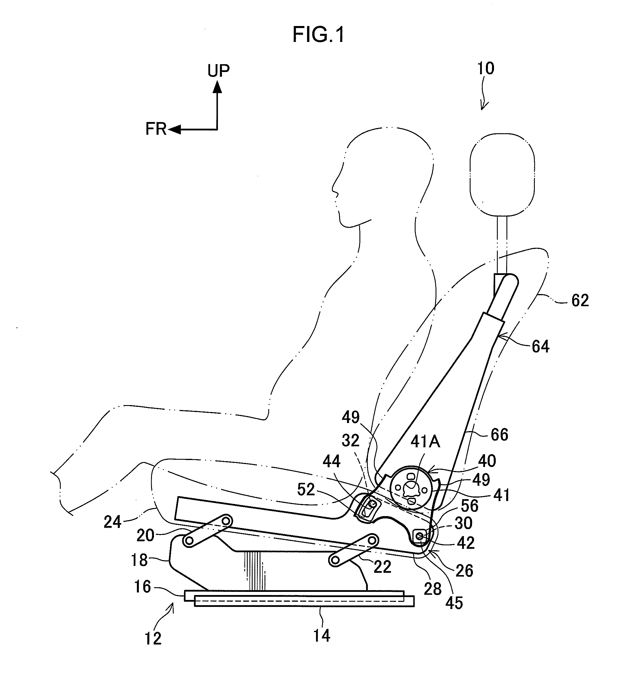
[0030]According to the vehicle seat according to the first aspect, the load imparted to the seatback frame can be stably absorbed, and can be efficiently absorbed.
[0031]According to the vehicle seat according to the second aspect, influence to the reclining mechanism can be suppressed when the weak portion is plastically deformed by the fixing portion.
[0032]According to the vehicle seat according to the third aspect, good relative rotation of the coupling member centered on the coupling portion with respect to the cushion frame is achieved, and load imparted to the seatback frame in the vehicle rear direction can be absorbed.
[0033]According to the vehicle seat of the fourth aspect, the weak portion can be formed with a simple configuration, and movement of the coupling member can be guided by the elongated hole.
[0034]According to the vehicle seat of the fifth aspect, the portion of the weak portion squashed by the fixing portion can be easily pressed out to the width direction outside of the elongated hole.
[0035]According to the vehicle seat according to the sixth aspect, the load imparted to the seatback frame can be effectively absorbed.

Problems solved by technology

However, when an impact load is imparted to the backrest structure in the vehicle rear direction, the adapter rotates about the pivot, the connection portion between the hole and the cutout portion makes contact with the fixing screw and is broken (deformed).

Method used


Image

  • Vehicle seat
  • Vehicle seat
  • Vehicle seat

Examples


modified example 1

[0073]The configuration of a modified example 1 is similar to that of the present exemplary embodiment, however differs in the following points.

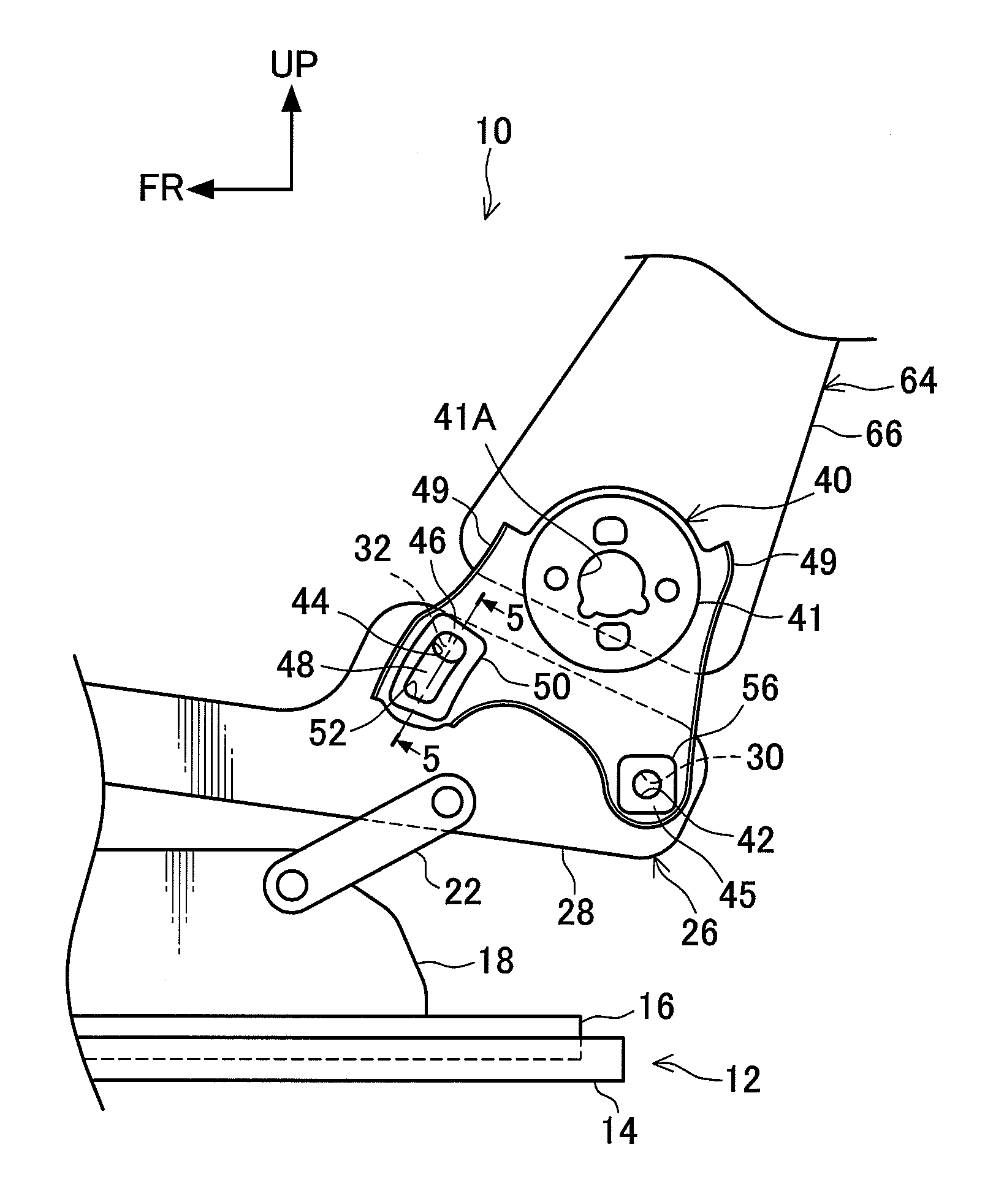
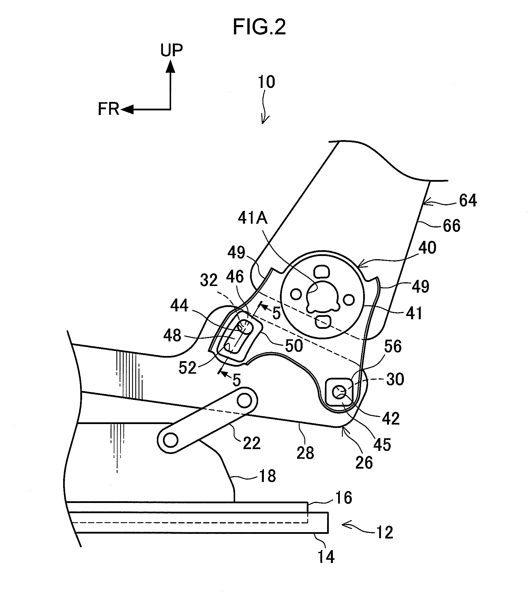
[0074]As illustrated in FIG. 6, in the modified example 1, a width dimension of the guide hole 52 of the fixing plate 50 is set so as to become larger on progression in a direction away from the fixing hole 44 (downward).

[0075]Thus when the hinge base bracket 40 relatively moves with respect to the fastening bolt 60, a portion of the weak portion 48 that is pressed and squashed by the fastening bolt 60 can be easily pressed out to the width direction outside of the guide hole 52.

modified example 2

[0076]The configuration of a modified example 2 is similar to that of the present exemplary embodiment, however differs in the following points.

[0077]As illustrated in FIG. 7, in the modified example 2, the width dimension of the guide hole 52 of the fixing plate 50 is set so as to become smaller on progression in a direction away from the fixing hole 44 (downward).

[0078]Thus the guide hole 52 is plastically deformed so as to be gradually pressed out to be widened by the fastening bolt 60 when the hinge base bracket 40 relatively moves with respect to the fastening bolt 60. The load imparted to the seatback frame 64 can hence also be absorbed by deformation of the fixing plate 50. The load imparted to the seatback frame 64 can accordingly be absorbed effectively.

[0079]Note that in the present exemplary embodiment, the modified example 1, and the modified example 2, the fixing plate 50 is joined to the hinge base bracket 40 by welding. However in place of this the fixing plate 50 may...


PUM


Abstract

Load imparted to a seat back frame is stably absorbed and efficiently absorbed. In a vehicle seat 10, a weak portion 48 is formed by a fixing plate (50). The weak portion (48) continuously extends from an edge portion of a fixing hole (44) in the relative movement direction with respect to a hinge base bracket (40) of a fastening bolt. Thus the weak portion (48) presses against the fastening bolt when the hinge base bracket (40) rotationally moves about the axial line of a support hole (42). Moreover, when the weak portion (48) plastically deforms, deformation so as to press the weak portion (48) wider is suppressed, such that the weak portion (48) is deformed so as to be squashed. Consequently, load imparted to a seatback frame (64) can be stably absorbed by the weak portion (48). Moreover, due to the weak portion (48) continuously plastically deforming when the weak portion (48) is plastically deformed by the fastening bolt, the load imparted by the weak portion (48) to the seatback frame (64) can be efficiently absorbed.

Description

TECHNICAL FIELD[0001]The present invention relates to a vehicle seat equipped with a coupling member that couples together a cushion frame and a seatback frame.BACKGROUND ART[0002]In the vehicle seat described in Japanese Patent Application Laid-Open (JP-A) No. 2008-238969, a seating portion is provided, and a seatback is coupled to the seating portion. The seatback includes a lower portion frame, and a first pin and a second pin are provided to the lower portion frame. The seatback includes side frames, and a first through hole and a second through hole are formed to each of the side frames. An auxiliary hole portion is in communication with the second through hole, and the auxiliary hole portion is open to the second through hole side. The side frames are coupled to the lower portion frame by inserting the first pin through the first through hole, and inserting the second pin through the second through hole.[0003]However, when an impact load is imparted to the seatback in the vehi...

Claims


Application Information

Patent Timeline
Patent Type & Authority Applications(United States)
IPC IPC(8): B60N2/42B60N2/68B60N2/427
CPCB60N2/4228B60N2/68B60N2/42745B60N2/42709B60N2/682
Inventor MUNEMURA, NOZOMUNAKANE, HIRONOBUNAGAHARA, RYONAGAI, KENSUKE
Owner NHK SPRING CO LTD
Why Eureka
Try Eureka