
In-vehicle camera

a technology for vehicles and cameras, applied in closed circuit television systems, color television details, television systems, etc., can solve the problem of large hood length, and achieve the effect of shortening the hood length

Active Publication Date: 2015-02-12
DENSO CORP
View PDF6 Cites 58 Cited by
  • Summary
  • Abstract
  • Description
  • Claims
  • Application Information

AI Technical Summary

Benefits of technology

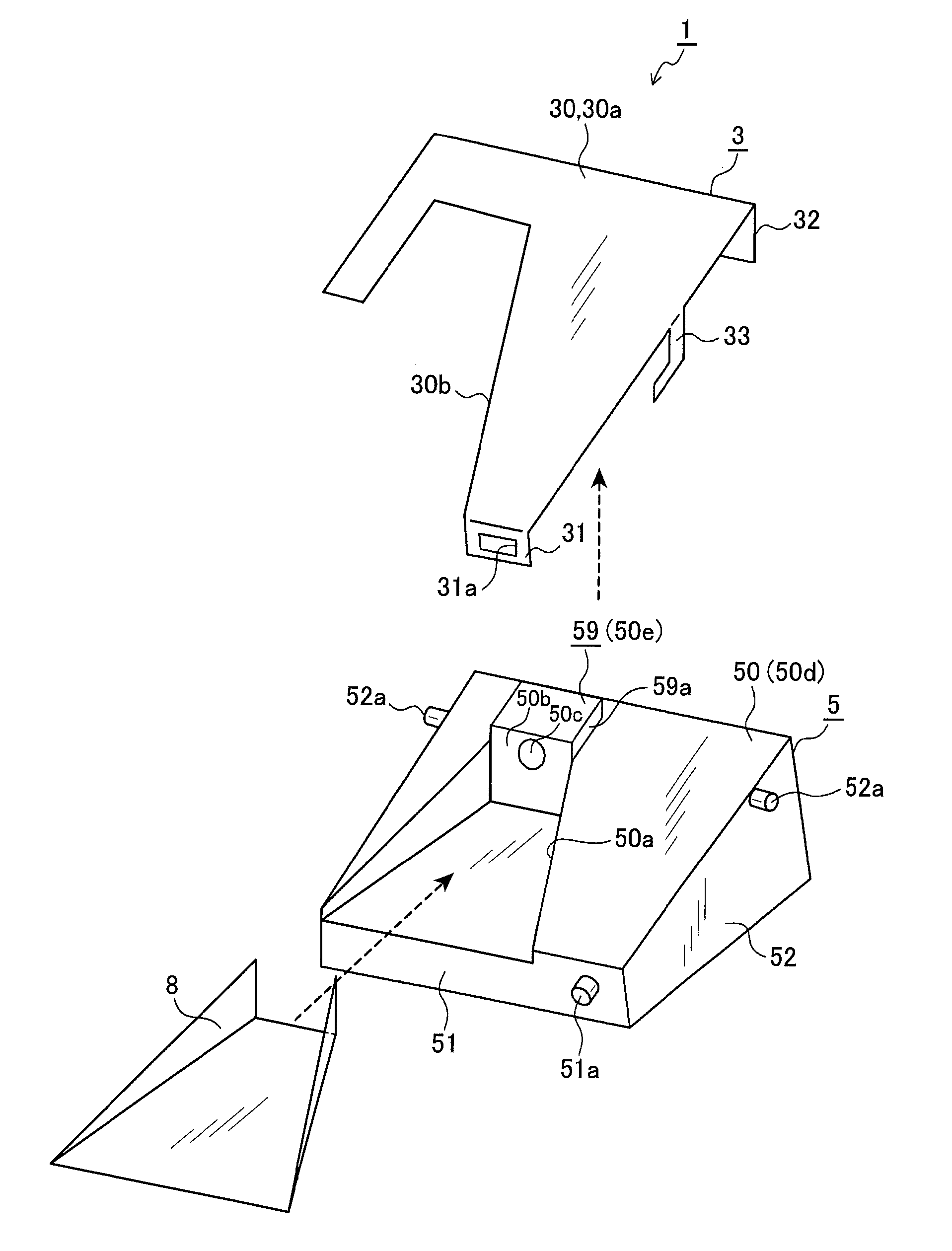
The technical effect of the patent text is to provide an in-vehicle camera that can capture a larger area of a bracket attached to a windshield and simultaneously shorten the length of the hood.

Problems solved by technology

However, the in-vehicle camera having such a structure also has a problem where the length of the hood is large especially when the inclination angle of the windshield is large.
Further, the in-vehicle camera having such a structure also has another problem where there is a need for securing a large area of a surface, which is attached to the windshield, of the bracket, in view of preventing the in-vehicle camera from dropping from the windshield.

Method used


Image

  • In-vehicle camera
  • In-vehicle camera
  • In-vehicle camera

Examples


Embodiment Construction

[0021]Hereinafter, an embodiment of the present invention is described with reference to the drawings.

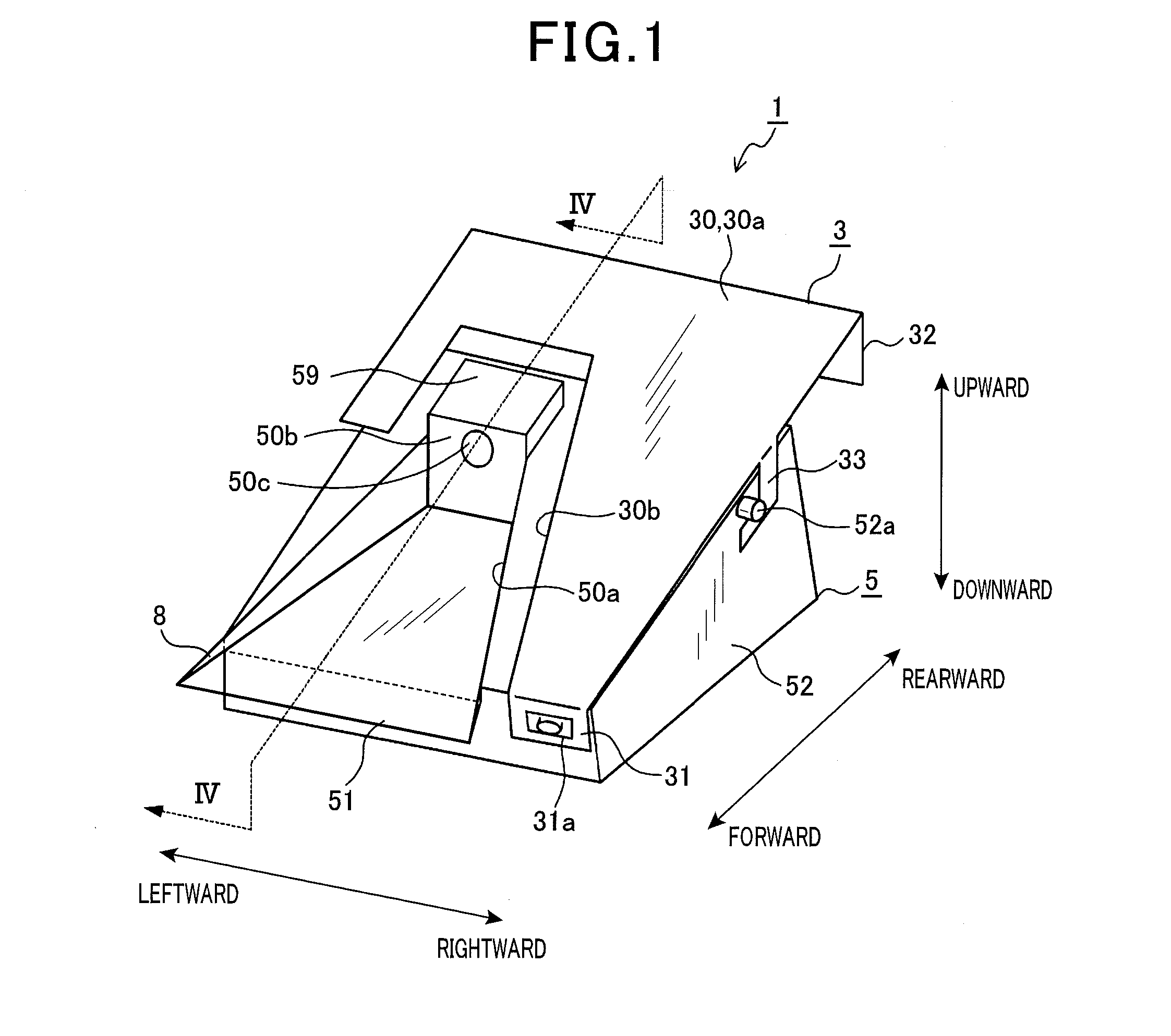
[0022]An in-vehicle camera of the present invention is used for imaging and monitoring the conditions ahead of the vehicle. In the following description, a forward direction is defined to be a direction to which the in-vehicle camera is oriented in a state where the in-vehicle camera is correctly mounted to the windshield of the vehicle at a predetermined position thereon to image the conditions ahead of the vehicle.

[0023]Further, the terms rearward, rightward, leftward, upward and downward used in the following description are the directions based on triangular projection with the forward direction relative to the vehicle being a front (indicated by arrows in FIG. 1), and thus the description referring such as to plan views or rear views is also based on triangular projection.

General Structure

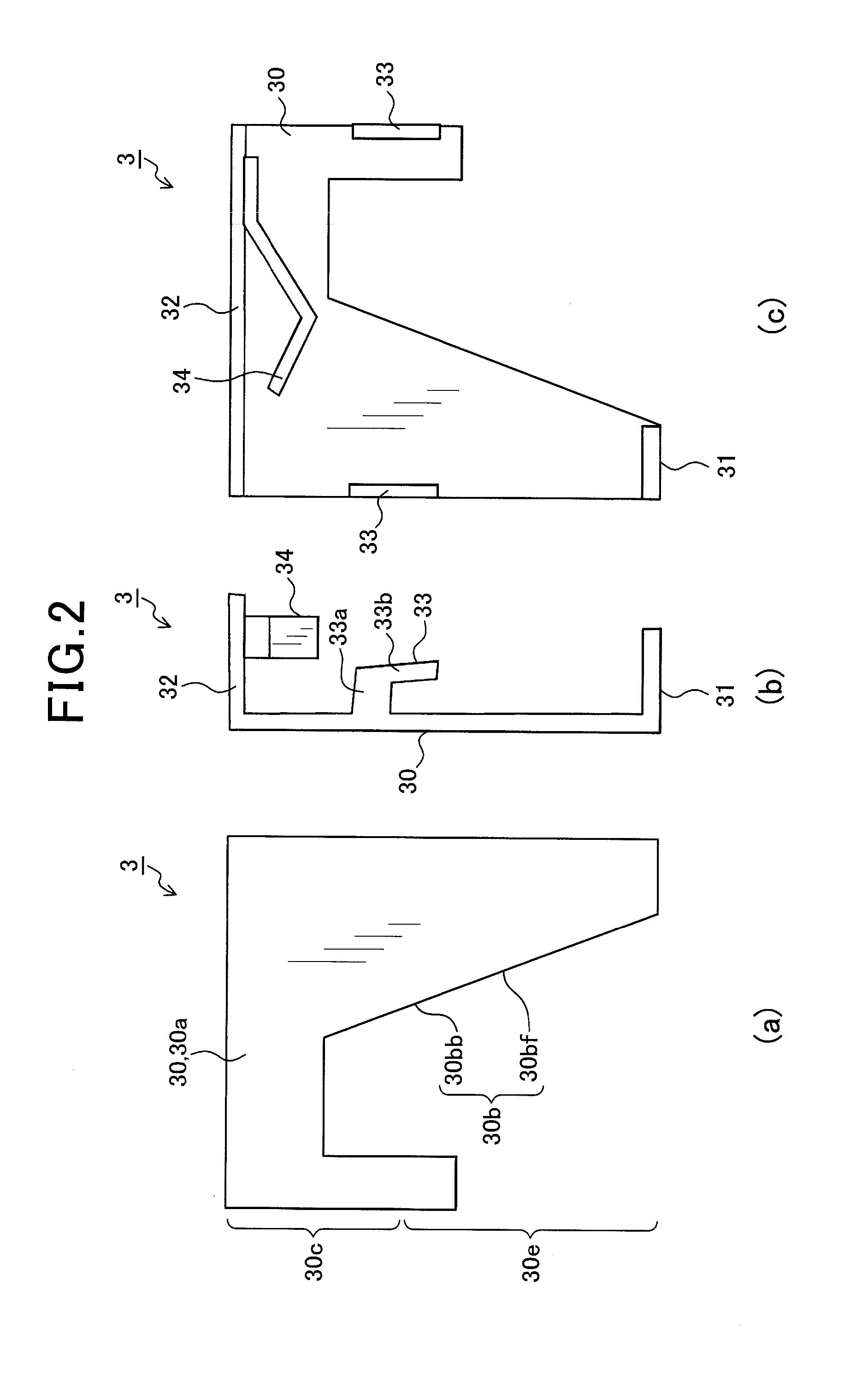
[0024]As shown in FIG. 1, an in-vehicle camera 1 of this embodiment includes a bracket 3 t...


PUM


Abstract

A vehicle-mounted camera has a lens disposed on a protruding part, which protrudes from the upper surface of a vehicle-mounted camera body; thus, compared to the situation in which the entire vehicle-mounted camera body is positioned below a bracket, the lens can be positioned at the shortest distance from a windshield, thereby enabling the length of a hood to be reduced. Furthermore, the in-vehicle camera is able to take up a large area of the portion of the bracket affixed to the windshield.

Description

CROSS REFERENCE TO RELATED APPLICATIONS[0001]This application is a U.S. National Phase Application under 35 U.S.C. 371 of International Application No. PCT / JP2013 / 055632 filed on Mar. 1, 2013 and published in Japanese as WO 2013 / 146093 A1 on Oct. 3, 2013. This application is based on and claims the benefit of priority from Japanese Patent Application No. 2012-074641 filed on Mar. 28, 2012. The entire disclosures of all of the above applications are incorporated herein by reference.TECHNICAL FIELD[0002]The present invention relates to an in-vehicle camera that is attached to a windshield of a vehicle from inside.BACKGROUND ART[0003]A conventional in-vehicle camera that monitors the conditions ahead of the vehicle has a structure where a casing is mounted to a ceiling of the vehicle, the casing has an opening in a surface facing the windshield, and the camera is disposed inside the casing.[0004]Since the casing of the in-vehicle camera has the opening in the surface facing the windshi...

Claims


Application Information

Patent Timeline
IPC IPC(8): B60R11/04
CPCB60R11/04B60R2011/0026B60R2011/0075B60R2011/0033B60R2011/0071B60R2011/0059
Inventor OKUDA, SYO
Owner DENSO CORP
Learn More