Catadioptric system and image pickup apparatus including the system

a catadioptric system and image pickup technology, applied in the field of optical systems, can solve the problems of insufficient size of the wavelength range in which the various aberrations or the telecentric property are satisfactorily maintained, and the size of the observation range is not necessarily sufficient for certain applications, and achieves high telecentric property, wide image pickup area, and high resolution power

Inactive Publication Date: 2015-02-12
CANON KK
View PDF1 Cites 4 Cited by
  • Summary
  • Abstract
  • Description
  • Claims
  • Application Information

AI Technical Summary

Benefits of technology

[0011]This disclosure provides an image pickup apparatus including a catadioptric system in which various aberrations are satisfactorily corr

Problems solved by technology

However, this method of presenting image data for observation takes a long time to take an image of the pathological specimen and import the image as image data.
However, the size of an observation range is not necessarily sufficient for certain appl

Method used


Image

  • Catadioptric system and image pickup apparatus including the system
  • Catadioptric system and image pickup apparatus including the system
  • Catadioptric system and image pickup apparatus including the system

Examples


example 1

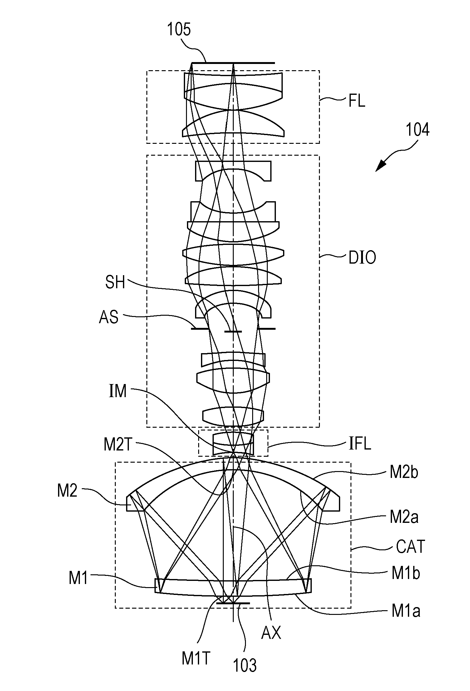
[0051]In Example 1, the conditional expressions (2a) and (2b) are satisfied by a configurations of the cemented lens formed by cementing a pair of the positive lens IFLp1 and the negative lens IFLn1 included in the intermediate field lens IFL and adjacent to each other. Then, the telecentric property is satisfactorily maintained while correcting the various aberrations satisfactorily over the entire visual light range.

[0052]In the catadioptric system of Example 1, the numerical aperture NA on the object side is 0.7, and the imaging magnification is 4 times, and the height of the object of the sample 103 is φ7 mm. Both the object side and the image side are configured to be telecentric, and the difference of the telecentric property for each color is restrained to a level lower than 0.1 degree. The error of the wavefront aberration in white light is restrained to a level not higher than 100 mλ (rms).

example 2

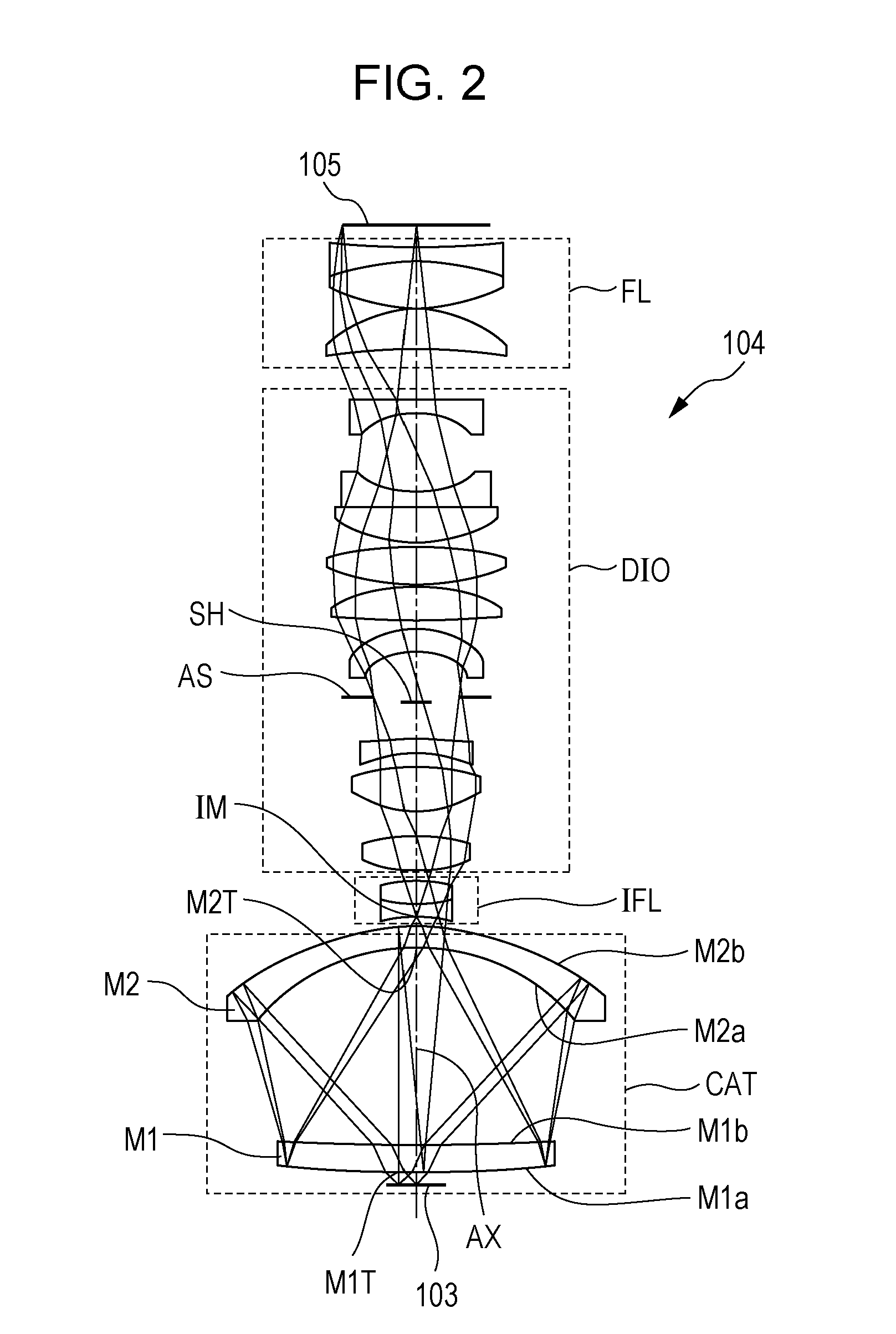
[0053]In Example 2, a pair of the positive lens FLp1 and the negative lens FLn1 of the image-side field lens FL are composed of independent lenses, and satisfy the conditional expressions (2a) and (2b), so that the telecentric property is satisfactorily maintained while correcting the various aberrations satisfactorily over the entire visual light range.

[0054]In the catadioptric system of Example 2, the numerical aperture NA on the object side is 0.7, and the imaging magnification is 6 times, and the height of the object of the sample 103 is φ7 mm. Both the object side and the image side are configured to be telecentric, and the difference of the telecentric property for each color is restrained to a level lower than 0.1 degree. The error of the wavefront aberration in white light is restrained to a level not higher than 100 mλ (rms).

Example 3

[0055]In Example 3, the catadioptric unit CAT includes the aperture stop AS in the interior thereof. In the catadioptric system of Example 3, ...

numerical example 1

[0060]

SurfaceNumberrdNdνdObject4.548735Surface1521.483310.4277851.6364.1421198.53771.914453−83.59067.35646451.6364.144−113.055−7.3564651.6364.145−83.5906−71.914561198.537−10.427851.6364.147521.483310.4277851.6364.1481198.53771.914459−83.59067.35646451.6364.1410−113.0553.04087611−188.335.0718291.7533.921246.257328.7761661.4969.9313−51.3793.4573971453.6319812.823611.5167.6215−88.34588.8790211646.1725516.254611.7147.5917−93.11654.72248818−70.456551.7529.1119−275.96832.307820−26.55338.2053581.7627.5821−35.48041.414069221.00E+181.41853923393.170212.663151.6350.2624−78.97290.52598.3662213.972331.5763.3926−141.891.2566782760.337813.116881.7531.2028−994.5440.58897929−1169.765.1033761.7531.583048.4666428.3576531−33.140951.6137.2732831.64118.7234433−153.46414.112471.6456.8734−51.92620.53574.5658616.865571.6259.5636−112.8551.6831.6037211.60568.620272ImagesurfaceCoefficient of aspherical surfaceSurfaceNumber 1, 7k = 0.00E+00 A = 4.09E−08 B = −1.52E−12 C = 6.23E−16D = −8.34E−20 E = 1.82E−23 F = ...


PUM


Abstract

A catadioptric system includes: a catadioptric unit configured to form an intermediate image of an object; a refracting portion configured to form an image of the intermediate image; a first field lens configured to guide optical flux from the catadioptric unit to the refracting portion; and a second field lens configured to guide the optical flux from the refracting portion toward an image side. The first and the second field lenses each include a positive lens and a negative lens adjacent to each other, and wherein where νIFLp1 and νIFLn1 are respectively Abbe numbers of materials of the positive lens and the negative lens of the first field lens, and νFLp1 and νFLn1 are respectively Abbe numbers of materials of the positive lens and the negative lens of the second field lens, conditions
20<νIFLp1−νIFLn1 and
20<νFLp1−νFLn1
are satisfied.

Description

BACKGROUND OF THE INVENTION[0001]1. Field of the Invention[0002]This disclosure relates generally to optical systems and in particular to an image pickup apparatus suitable for observing a sample (object) at an enlarged scale.[0003]2. Description of the Related Art[0004]In pathological examination, a pathological specimen (sample) is directly observed with a human eye by using an optical microscope. In recent years, a so-called “virtual microscope” configured to import a pathological specimen as image data and present the image data on a display for observation has been proposed and put in practical use. Since the virtual microscope allows observation of the image data of the pathological specimen on a large display, a plurality of persons can observe the image data on the display simultaneously. Usage of the virtual microscope has many advantages such that the image data can be shared with a pathologist at a distance to obtain his or her diagnosis. However, this method of presentin...

Claims


Application Information

Patent Timeline
IPC IPC(8): G02B17/08G02B21/00
CPCG02B21/0004G02B17/0804
Inventor KAJIYAMA, KAZUHIKO
Owner CANON KK
Why Eureka
Try Eureka