

Regulating member and developing device
a technology of developing device and regulating member, which is applied in the direction of instruments, electrographic process apparatus, optics, etc., can solve the problems of difficult observation of the gap state after the assembling, and achieve the effects of low rigidity, high accuracy and high accuracy
- Summary
- Abstract
- Description
- Claims
- Application Information
AI Technical Summary
Benefits of technology
Problems solved by technology
Method used
Image

Examples
embodiment 1
(Effect of Embodiment 1)
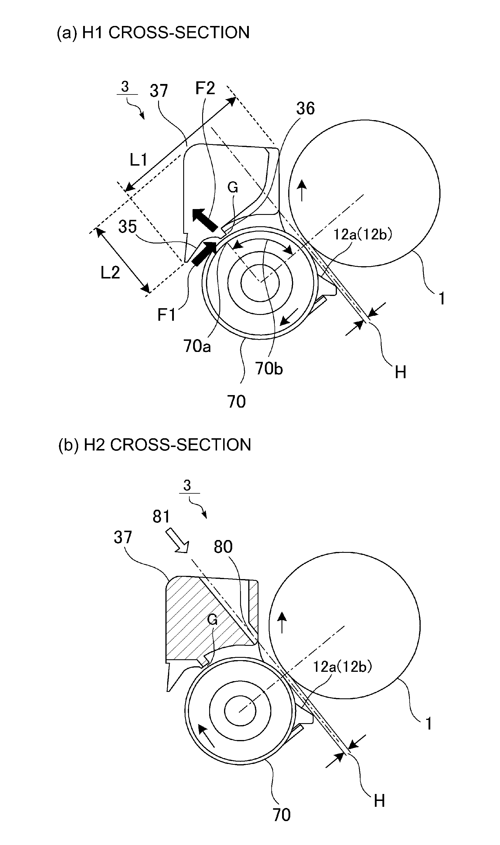
[0066]In the developing device 3 in Embodiment 1, even when the regulating member (sleeve holder frame) 37 is formed of an inexpensive material having low rigidity, necessary rigidity can be ensured by the cross-section shape projecting toward the photosensitive drum 1. In the developing device 3 in Embodiment 1, the SB gap G which is the interval between the developing sleeve 70 and the layer thickness regulating portion 36 is held and fixed with high accuracy, and thereafter the SD gap H which is the interval between the photosensitive drum 1 and the developing sleeve 70 can be adjusted and assembled with high accuracy.
[0067]In the developing device 3 in Embodiment 1, the SG gap G and the SD gap H can be set precisely and stably with high reproducibility, and therefore it is possible to provide a further downsized process cartridge. The developing device 3 in Embodiment 1 is capable of compatibly realizing reductions in size and weight of the process cartri...
embodiment 2
(Effect of Embodiment 2)
[0080]The developing device 3B in Embodiment 2 is provided with the gap 80, in the non-image region as each of the end portions of the regulating member 137, capable of ensuring a sight line to the SD gap H from above. For this reason, in a state in which the photosensitive drum 1, the regulating member 137 and the developing sleeve 70 are incorporated in the developing device 3B, the SD gap H can be accurately adjusted without damaging the photosensitive drum 1 in the image region. The developing device 3B in Embodiment 2 is capable of providing a stable image density of the output image since the gap between the photosensitive drum 1 and the developing sleeve 70 can be adjusted with high accuracy.
[0081]In the developing device 3B in Embodiment 2, the regulating member 137 including the layer thickness regulating portion 36 is a molded product obtained by the injection molding of the resin material, and therefore a component cost of the image forming apparat...
embodiment 3
[0083]The present invention can be carried out also in other embodiments in which a part or all of constituent elements in the above-described embodiments are replaced with alternative constituent elements thereof so long as the regulating member form regulating the layer thickness of the developer is provided with the through hole through which the SD gap is visually recognizable. Accordingly, the present invention is not limited to the developing device using the two-component developer, but may also be carried out in a developing device using a one-component developer. The present invention is not limited to the developing device in the form of the process cartridge, but may also be carried out in a developing device capable of being mounted and dismounted alone for exchange. The present invention is not limited to the full-color image forming apparatus, but may also be carried out in a monochromatic image forming apparatus including the developing device or the process cartridge...
PUM
 Abstract
Description
Claims
Application Information