Heat exchanger mounting structure

a technology of mounting structure and heat exchanger, which is applied in the direction of indirect heat exchangers, machines/engines, light and heating apparatus, etc., can solve the problems of affecting the stability of transmission, and affecting the efficiency of transmission, so as to achieve stable state, reduce looseness, and efficiently transmit

Active Publication Date: 2015-02-19
DENSO CORP
View PDF13 Cites 14 Cited by
  • Summary
  • Abstract
  • Description
  • Claims
  • Application Information

AI Technical Summary

Benefits of technology

[0012]Accordingly, the load of the one of the heat exchangers having the bracket is supported by the load supporting section prepared to the other heat exchanger. Furthermore, due to the load supporting section and the fitting member fitted to the outer side of the load supporting section, the load of the one of the heat exchangers having the bracket is supported in the up-and-down direction and in the left-and-right direction. Thereby, the heat exchangers can be assembled in the stabilized state in the up-and-down direction and the left-and-right direction. Furthermore, if one of the heat exchangers is deviated in a direction separating from or approaching to the other heat exchanger, at least a part of the bracket is pressed downward by the contact section. Thereby, if one of the heat exchangers is deviated in a direction separating from or approaching to the other heat exchanger, the deviation dimension is regulated by the contact section. Therefore, the attachment state of the heat exchangers is stabilized also in the front-and-rear direction of the heat exchangers, and the stable state can be maintained. Thus, the looseness can be reduced in the heat exchanger mounting structure irrespective of the size of front-and-rear interval between the two heat exchangers.
[0013]For example, the contact section is placed to the fitting member at a position located right above the load supporting section. Since the contact section presses down the fitting member which is in direct fitting to the load supporting section, the pressing force of the contact section can be efficiently transmitted to the heat exchanger having the bracket. Therefore, the deviation dimension of the heat exchanger can be further reduced.
[0014]For example, the contact surface of the contact section in contact with the upper surface of the bracket is equipped with a sloped surface which is sloped upward as extending toward the tip end of the contact surface. Thereby, while the heat exchangers are mounted, when a portion of the bracket which is pressed down by the contact section is place under the contact section, the portion of the bracket can be arranged smoothly by inserting from the tip end of the contact surface. Therefore, the workability of mounting the heat exchangers can be improved.
[0015]For example, the contact section has the contact surface in contact with the upper surface of the bracket, and a rib extending in a direction crossing the contact surface. According to this, the strength of the contact section itself can be improved.

Problems solved by technology

In this art, the condenser is mounted to the radiator using a plastic bracket, however, a slight looseness may arise between the components.
In case of such a mounting structure, when the looseness caused by wear in the component, for example by aging etc., is increased, the connector may be broken, or there is a possibility such as breakage by interference between the radiator and the condenser.
In case where the multiple kinds of radiators are used, with Patent document 3, if the width dimension of the heat exchange core part of the radiator is small in the front-rear direction, the stopper cannot appropriately be in contact with the radiator, and cannot achieve the function.
Furthermore, if the condenser located on the front side deviates frontward, the stopper cannot achieve the function.

Method used


Image

  • Heat exchanger mounting structure
  • Heat exchanger mounting structure
  • Heat exchanger mounting structure

Examples


first embodiment

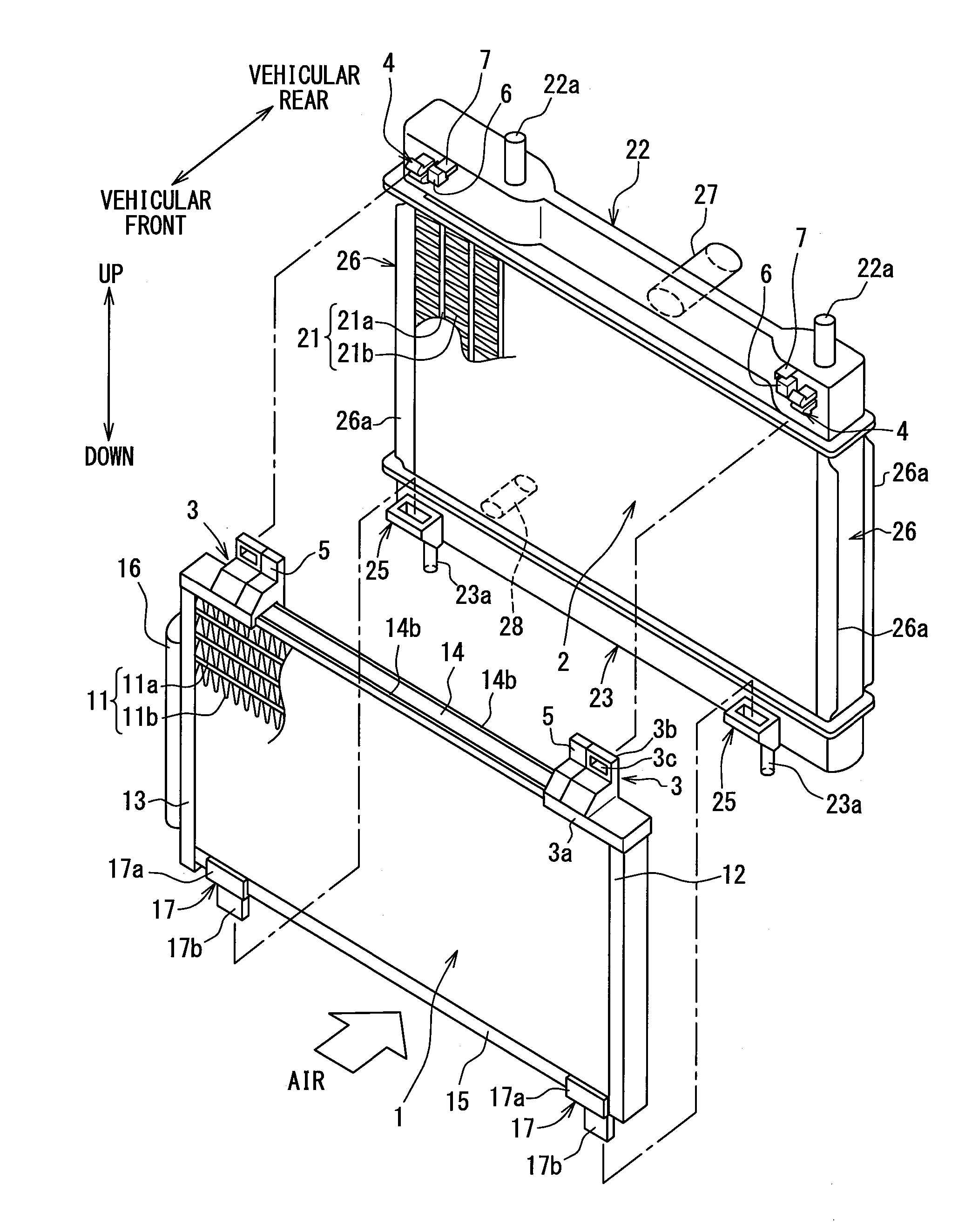
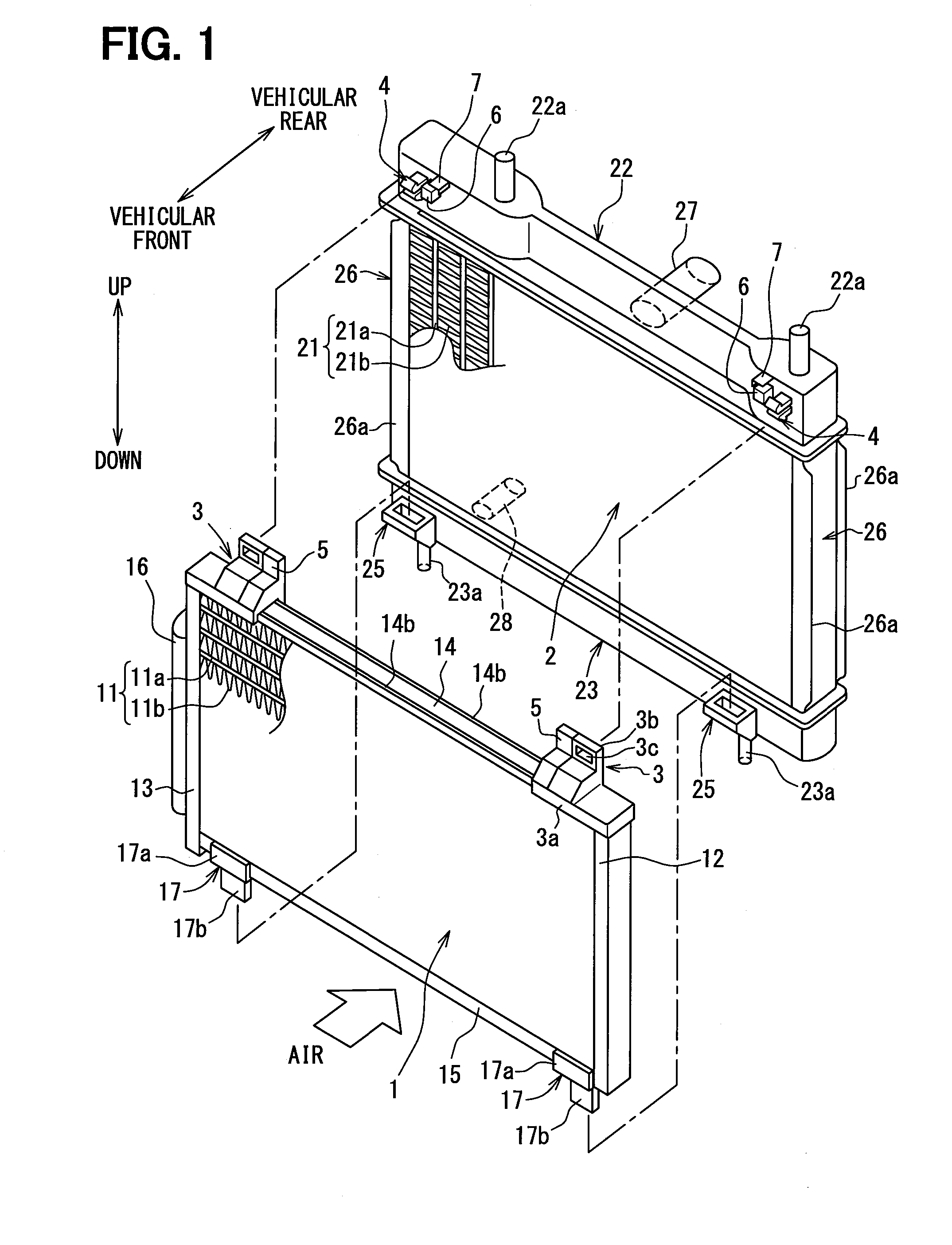
[0036]A heat exchanger mounting structure according to a first embodiment of the present disclosure is explained with reference to FIGS. 1-8. The heat exchanger mounting structure of this embodiment relates to a structure of mounting heat exchangers arranged in a predetermined state certainly so that the heat exchange core parts oppose each other. FIG. 1 is an exploded perspective view illustrating a schematic structure of mounting a condenser 1 and a radiator 2 as example of two heat exchangers. FIG. 2 is an enlarged perspective view illustrating a partial structure of the radiator 2. FIG. 3 is an enlarged perspective view illustrating a partial structure of the condenser 1 and the radiator 2.

[0037]As shown in FIG. 1, the condenser 1 and the radiator 2 are disposed adjacent with each other in an engine compartment of a vehicle. The condenser 1 is an example of a first heat exchanger, and is arranged on the vehicular front side (front part of the engine compartment) or upstream side...

second embodiment

[0076]A second embodiment is a modification example of the heat exchanger mounting structure of the first embodiment, and is explained using FIG. 9 and FIG. 10. FIG. 9 is a front view explaining the relationship among the bracket 3B, the fitting member 5, the load supporting section 6, the pressed part 5a, and the pressing part 7A and the pressing part 7B in the second embodiment. FIG. 10 is a front view explaining other example further equipped with the top plate part 8A on the pressing part 7A shown in FIG. 9. The components having the same mark and code as the first embodiment in FIG. 9 and FIG. 10 are similar components having the same operation and the same effect.

[0077]As shown in FIG. 9, the heat exchanger mounting structure of the second embodiment has the pressed part 5a which is pressed down by the pressing part 7A, 7B from the upper side. The pressed part 5a is located at a position lower than the upper end of the bracket 3B, and integrally extends from the bracket 3B on ...

third embodiment

[0082]A third embodiment is a modification example of the heat exchanger mounting structure of the first embodiment, and is explained using FIG. 11 and FIG. 12. FIG. 11 is a front view explaining the relationship among the bracket 3D, the fitting member 5A, the load supporting section 6A, and the pressing part 7B in the third embodiment. FIG. 12 is a front view explaining other example further having the top plate part 8B on the pressing part 7B shown in FIG. 11. The components having the same mark and code as the first embodiment in FIG. 11 and FIG. 12 are similar components having the same operation and the same effect.

[0083]As shown in FIG. 11, the fitting nail 4 and the load supporting section 6A are arranged in the up-and-down direction. The load supporting section 6A is disposed at each of the upper side and the lower side of the fitting nail 4. The fitting member 5A surrounds each of the upper load supporting section 6A and the lower load supporting section 6A, and is fitted ...


PUM


Abstract

A heat exchanger mounting structure is provided with a bracket, a load supporting section, a fitting member, and a contact section. The bracket is provided to one of a first heat exchanger and a second heat exchanger. The load supporting section is provided to the other heat exchanger to which the bracket is not provided, and supports a load transmitted from the one of the first heat exchanger and the second heat exchanger. The fitting member is provided to the one of the first heat exchanger and the second heat exchanger, to which the bracket is provided, and is fitted over the load supporting section. The contact section is in contact with at least a part of the upper portion of the bracket.

Description

CROSS REFERENCE TO RELATED APPLICATION[0001]This disclosure is based on Japanese Patent Application No. 2011-286443 filed on Dec. 27, 2011, the disclosure of which is incorporated herein by reference in its entirety.TECHNICAL FIELD[0002]The present disclosure relates to a heat exchanger mounting structure.BACKGROUND ART[0003]Patent document 1 and Patent document 2 disclose a conventional heat exchanger mounting structure in which a condenser or an electric fan is fixed to a radiator without using a connector such as bolt in vehicles. In this art, the condenser is mounted to the radiator using a plastic bracket, however, a slight looseness may arise between the components. In case of such a mounting structure, when the looseness caused by wear in the component, for example by aging etc., is increased, the connector may be broken, or there is a possibility such as breakage by interference between the radiator and the condenser. Therefore, it may be necessary to increase the interval b...

Claims


Application Information

Patent Timeline
Patent Type & Authority Applications(United States)
IPC IPC(8): F28F9/007
CPCF28F9/007F01P2003/182F01P2070/52F28D1/0435F28D1/05366F28D2021/008F28F9/002F28F9/02F28F9/262F28F2275/085
Inventor TAKAHASHI, KENTAROSUMIYA, SATOSHIODA, SHINICHI
Owner DENSO CORP
Why Eureka
Try Eureka