Exhaust nozzle and method for changing exhaust flow path

Active Publication Date: 2015-02-19
JAPAN AEROSPACE EXPLORATION AGENCY
View PDF15 Cites 3 Cited by
  • Summary
  • Abstract
  • Description
  • Claims
  • Application Information

AI Technical Summary

Benefits of technology

The present invention aims to provide an exhaust nozzle and a method for changing an exhaust flow path that can reduce noise without adding complexity and size to the structure of the exhaust nozzle. Additionally, it improves efficiency during cruising at supersonic speeds.

Problems solved by technology

When high-pressure fluid, such as exhaust from an engine, is discharged from an exhaust nozzle, which forms an exhaust flow path, a high-speed fluid is created at the end of the nozzle, this high-speed fluid spreads while mixing with surrounding fluid according to a speed gradient with respect to the surrounding fluid, and noise is generated in this course of this mixing action.
In particular, in the exhaust portion of a jet engine in an aircraft or the like, the noise has high energy across a broad frequency band, and areas adjacent to an airport and the aircraft passengers suffer barely acceptable effects due to exposure to noise, especially during take-off and landing.
The technology disclosed in Japanese Patent Application Publication No. 2007-285245 and Japanese Patent Application Publication No. 2008-144764 and Tsutomu OISHI, “Jet Noise Reduction by Notched Nozzle on Japanese ECO engine project”, AIAA Paper 2010-4026 makes no mention at all of efficiency when cruising at supersonic speeds, and if these common technologies are applied to a supersonic aircraft, then in order to improve efficiency when cruising at supersonic speeds, in addition to the movable mechanism of the exhaust nozzle, increases in complexity and size are required.
Furthermore, it is also necessary to consider whether or not an improvement in propulsion is obtained which is sufficient to compensate for the increase in complexity and size, and therefore it has been difficult to improve efficiency in a practicable fashion, simply by combining the structure for noise reduction disclosed in Japanese Patent Application Publication No. 2007-285245 and Japanese Patent Application Publication No. 2008-144764, and the like, and the mechanism for improving efficiency during supersonic cruising disclosed in Tsutomu OISHI, “Jet Noise Reduction by Notched Nozzle on Japanese ECO engine project”, AIAA Paper 2010-4026, and the like.
These compositions are complex, and by providing these mechanisms, the weight is increased, and therefore even if an increase in propulsion that compensates for this weight increase is achieved, the improvement in efficiency during supersonic cruising is slight, and there is a problem in that it is impossible to avoid increase in manufacturing costs due to increased complexity and size, and increased labor time due to maintenance and inspection.

Method used


Image

  • Exhaust nozzle and method for changing exhaust flow path
  • Exhaust nozzle and method for changing exhaust flow path
  • Exhaust nozzle and method for changing exhaust flow path

Examples


Embodiment Construction

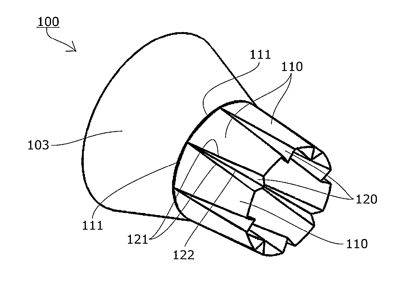
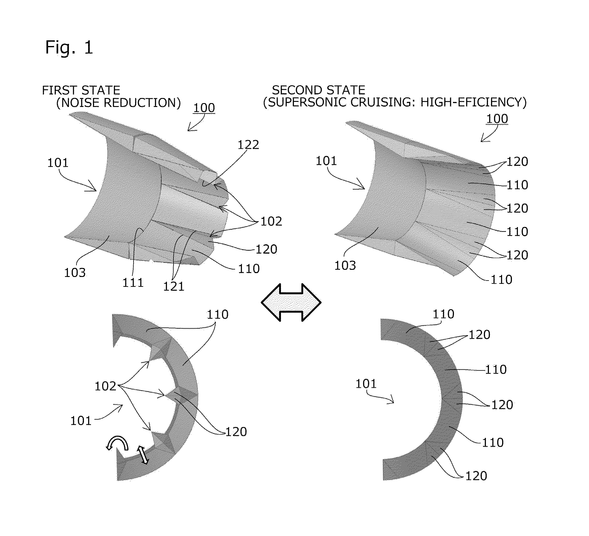
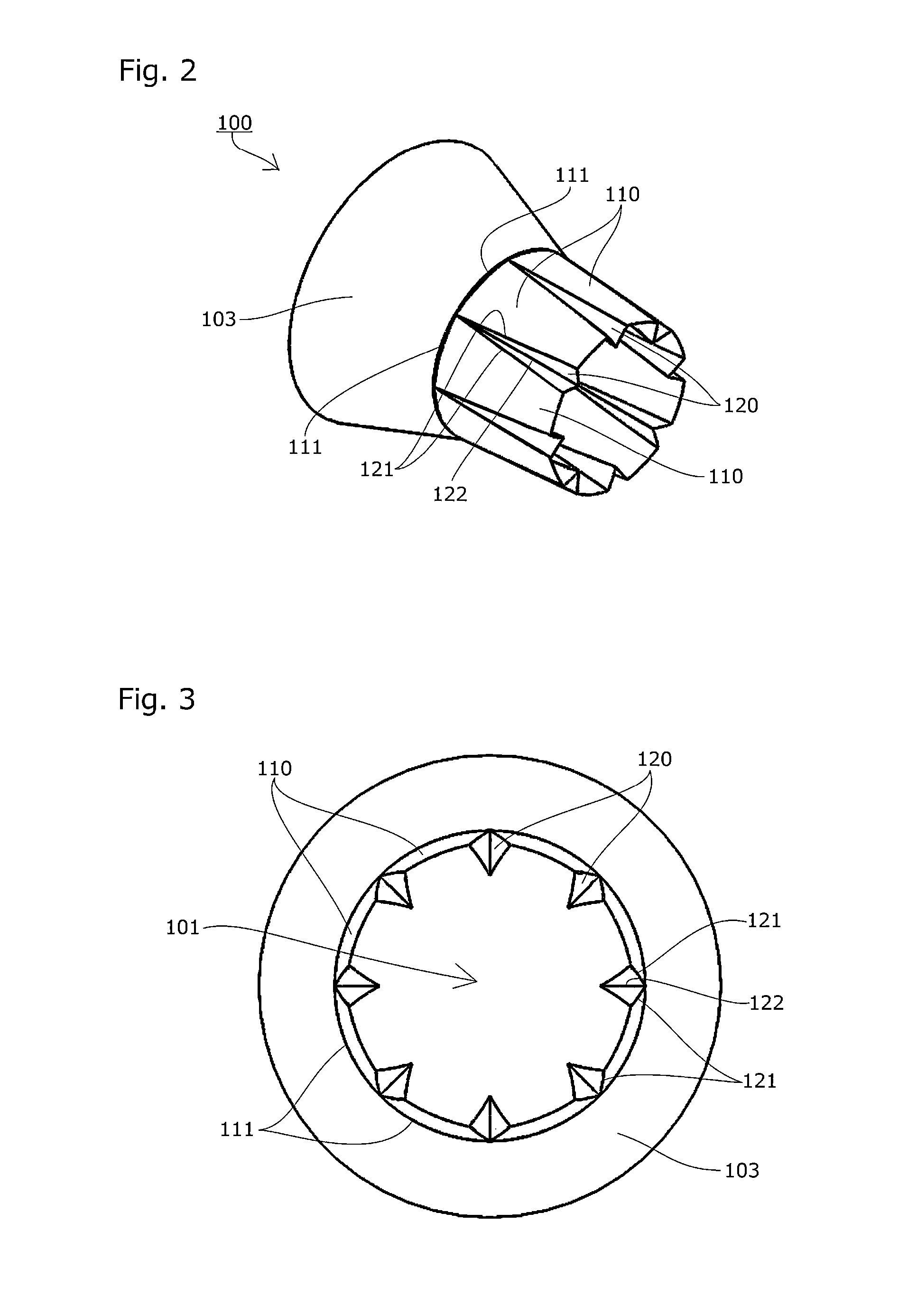
[0043]The exhaust nozzle according to the present invention is an exhaust nozzle extending to the rear of an engine and constituting an exhaust flow path, wherein the exhaust nozzle has a plurality of main nozzle pieces and at least one coupling nozzle piece; a rear end portion of each of the main nozzle pieces is provided swingably in an inward and outward direction of the exhaust flow path about an open / close bend section to the rear of the engine; the coupling nozzle piece is disposed between adjacent main nozzle pieces and is coupled bendably to the main nozzle pieces on either side thereof; when the main nozzle pieces are swung outward from the exhaust flow path, the coupling nozzle piece forms a flat surface having no projecting section inside the exhaust flow path; and when the main nozzle pieces are swung inside the exhaust flow path, the coupling nozzle piece forms a projecting section inside the exhaust flow path. The invention may be implemented by any embodiment, provide...


PUM


Abstract

Provided is an exhaust nozzle and a method for changing an exhaust flowpath, whereby noise can be reduced by using a simple and light-weight mechanism without increasing the complexity and size of the structure of the exhaust nozzle, and furthermore, the efficiency during cruising at supersonic speeds can be improved. The rear end side of main nozzle pieces 110 of an exhaust nozzle 100 are provided swingably in an inward and outward direction of an exhaust flow path 101, about an open / close bend section 111 to the rear of an engine, coupling nozzle pieces 120 are coupled bendably to adjacent main nozzle pieces 110 on either side, and when the main nozzle pieces 110 are swung inside the exhaust flow path 101, the coupling nozzle pieces 120 form projecting sections 102 inside the exhaust flow path 101.

Description

BACKGROUND OF THE INVENTION[0001]1. Field of the Invention[0002]The present invention relates to an exhaust nozzle extending to the rear of an engine and constituting an exhaust flow path, and to a method for changing an exhaust flow path whereby a cross-sectional shape of an exhaust flow path extending to the rear of the engine is altered, and in particular, to an exhaust nozzle and a method for changing an exhaust flow path suitable for an engine of a supersonic aircraft.[0003]2. Description of the Related Art[0004]When high-pressure fluid, such as exhaust from an engine, is discharged from an exhaust nozzle, which forms an exhaust flow path, a high-speed fluid is created at the end of the nozzle, this high-speed fluid spreads while mixing with surrounding fluid according to a speed gradient with respect to the surrounding fluid, and noise is generated in this course of this mixing action.[0005]In particular, in the exhaust portion of a jet engine in an aircraft or the like, the n...

Claims


Application Information

Patent Timeline
IPC IPC(8): F02K1/08
CPCF02K1/08F02K1/46Y02T50/60
Inventor AKATSUKA, JUNICHIWATANABE, YASUSHI
Owner JAPAN AEROSPACE EXPLORATION AGENCY
Why Eureka
Try Eureka